Continue to Site

Welcome to EDAboard.com

Welcome to our site! EDAboard.com is an international Electronics Discussion Forum focused on EDA software, circuits, schematics, books, theory, papers, asic, pld, 8051, DSP, Network, RF, Analog Design, PCB, Service Manuals... and a whole lot more! To participate you need to register. Registration is free. Click here to register now.

[Moved] Using Allpass Filter as 90 degree phase shift

Status
Not open for further replies.

Fikadu

Junior Member level 3
Joined
Feb 22, 2015
Messages
31
Helped
0
Reputation
0
Reaction score
0
Trophy points
6
Activity points
304
Sorry, I don't have much idea about Circuit design. I am trying to use allpass filter as 90 degree phase shifter. I just followed what stated in the link: https://en.wikipedia.org/wiki/All-pass_filter
Using upc815c as OP AMP with Rx = 5.1Ω , C =12pF and calculating R = 1/(2ΠfC) = 978Ω, where Power frequency f = 13.56MHz.

My problem is that amplitude of the output fluctuates too much and phase shift reading from input to output also fluctuates from negative to positive while testing on oscilloscope(like -130, -85 , -30,-5, 16,48,60,92,94,114,144..etc).
would you help me please why this happened?


Thank you a lot.
 

Re: Using Allpass Filter as 90 degree phase shift

upc815c has a gain bandwidth of 7 MHz and can't work in the intended frequency range. The OP slew rate restricts the useful large signal bandwidth to some 10kHz rather than MHz. Also the specified Rx value is several orders of magnitude too low.
 

Re: Using Allpass Filter as 90 degree phase shift

upc815c has a gain bandwidth of 7 MHz and can't work in the intended frequency range. The OP slew rate restricts the useful large signal bandwidth to some 10kHz rather than MHz. Also the specified Rx value is several orders of magnitude too low.


Thank you a lot for your help.
I just tried with 2MHz and the same thing happened. I don't get what wrong with it.
Thank you once again
 

It is a 90 degree phase shift (current versus voltage) which happens in every capacitor or inductor when AC goes through it. "Capacitor current leads, inductor current lags."

Your Wikipedia link has the schematic of an opamp-based all-pass filter. They point out that it needs no inductor. This suggests you can make an all-pass filter from an LC network. (In fact, the schematic has some resemblance to a gyrator circuit (active inductor).
Select L & C values which produce reasonable performance at your desired frequency, for your combination of voltage, Amperes, and neighboring resistances.

I've experimented with various schematics. I believe the rolloff curves for inductor and capacitor need to overlap in the correct manner, so that one curve is rising where the other is falling. Thus together they combine to produce unchanging output amplitude.
 

Please clarify about the actual component values and how you measured phase shift. An all-pass build with a 7 MHz OP can't give ideal behavior at 2 MHz, but should at least show some phase shift. More likely you have still unsuitable component values or some other circuit fault.

Please consider that the chosen OP can output 2 MHz signals only with small magnitude (e.g. below 100 mV) due to limited slew rate.

For good performance, the OP GBW should be factor 10 to 20 larger than operation frequency.


Thank you very much for your helpful suggestions.

The actual values of the components are follows:

Using upc815c as OP AMP with Rx = 9.1kΩ , R =4.7kΩ and calculating C = 1/(2ΠfR) = 16.9pF, where Power frequency f = 2MHz.

I just measured a phase shift from input to output on oscilloscope.

As you said, I will try to select OP AMP with the better performance. would you suggest me please?


By the way, I have also been trying to use LC Network as suggested in the following Link:
https://www.edaboard.com/showthread...0-deg-phase-shifter-design-for-2-5-8-GHz-band

I have calculated L and C values accordingly. But still , 90 degree phase shift couldn't be achieved.


Thank you once again.
 

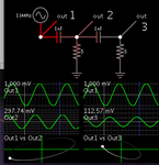
This simulation demonstrates phase shifts obtained from RC networks (equivalent of high-pass filters).
The first capacitor causes about 80 degrees shift.
The second capacitor causes much greater than 90 degrees shift.
These also cause amplitude changes, as seen from the captions.

two series caps resis to gnd show increa phase shift 13 MHz.png
 

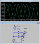
See below a simulation with an OP that has roughly similar specs as upc815c. As previously mentioned, due to limited slew rate, it can only process small signal magnitudes in a 100 mV range at 2 MHz.

allpass.PNG

There are many OPs with 10 to 50 MHz unity gain bandwidth and higher slew rate available. It must be unity gain stable to work in the all pass configuration.
 

I would like to extend many thanks.
I really appreciate your genuine help. It is really helpful
As you had mentioned before, I have tested using upc815c with low frequency, like 300kHz and it is working fine. I will buy an OP with high GBW and faster slew rate for the 13.56MHz.

Thank you a lot once again.
 

Status
Not open for further replies.

Similar threads

Part and Inventory Search

Welcome to EDABoard.com

Sponsor

Back
Top