Continue to Site

Welcome to EDAboard.com

Welcome to our site! EDAboard.com is an international Electronics Discussion Forum focused on EDA software, circuits, schematics, books, theory, papers, asic, pld, 8051, DSP, Network, RF, Analog Design, PCB, Service Manuals... and a whole lot more! To participate you need to register. Registration is free. Click here to register now.

Is a multi-phase buck-boost converter possible?

Status
Not open for further replies.

David_

Advanced Member level 2
Joined
Dec 6, 2013
Messages
573
Helped
8
Reputation
16
Reaction score
8
Trophy points
1,308
Location
Sweden
Activity points
12,220
Hello.

I have been reading about multi-phase synchronous buck-converters and there benefits compared to a ordinary buck-converter, and I have seen but not really read about multi-phase boost converters.
Multi-phase converter means that instead of having a synchronous buck-converter built with one power stage(high-side & low-side MOSFET switches, inductor and possibly capacitors) you make several individual buck-converters that are connected parallel and by some means share the current load, which is a scheme that offers a hole load of useful results.

Anyway what I wonder is this, what about a multi-phase buck-boost converter?

What is the reason for why I can't find a single reference to such a circuit online?

I am trying to design a high-current 4-switch non-inverting buck-boost converter, high current being 45A while low voltages below 8,4V, and I was simply entertaining the idea of a dual-phase buck-boost converter which I admit sounds sort of strange and maybe even impractical given the amount of MOSFET's and MOSFET drivers that would entail, if I imagine such a converter with 3 phases then it starts to get out of hand. Could that be the answer, that a multi-phase buck-boost converter simply isn't practical due to the benefits of multiple phases not justifying the increase in the physical circuit and number of components?

Regards
 

If I were experimenting with a power supply consisting of several switched converters, I would make a control interface made up of inexpensive components, easily adjustable, easily replaceable.
I have tried to resist using IC's that are prone to break at first use if I didn't get everything right. It's not the modern engineer's approach, it's the tightwad hobbyist approach.

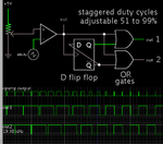
This control circuit is a D flip-flop and OR gates, arranged to distribute incoming clock pulses to two converters, so that they are staggered evenly. Their duty cycle is determined by a single potentiometer setting in the clock pulse generator.

D flip-flop and 2 OR gates distrib 2 pulses 51-99 pct.png

By changing the type of logic gates, it provides duty cycles of 1 to 50 percent.

Three flip-flops can be assembled into a shift register, to control 3 converters by giving staggered 'On' commands. As before, a single potentiometer is sufficient to control duty cycle for all converters.
 
  • Like
Reactions: David_ and d123

    d123

    Points: 2
    Helpful Answer Positive Rating

    David_

    Points: 2
    Helpful Answer Positive Rating
Multi-phase buck-boost is of course feasible and used in high power applications. It's however mostly using the topology boost-DCLink-buck. Paralleling multiple 4-switch/single-inductor buck-boost converter is nevertheless possible and e.g. supported by a sync feature of existing controller chips.

I don't understand about "starts to get out of hand". Multi-phase is used for a purpose, particularly reducing input and output ripple current. If it pays the effort, you'll use as many phases as useful.
 
  • Like
Reactions: David_

    David_

    Points: 2
    Helpful Answer Positive Rating
Hi David, I hope you are well. Nice to see you again. Is this for the vape device or another circuit? I don't know if it would help - Is researching a bit about interleaved supplies a way to source pertinent information? I don't know about that stuff.

Hi FvM, he meant pcb real estate, it would be a sprawling circuit I guess. As a hobbyist it always seems hard to make a circuit as small as one might prefer.
 

In some cases the ripple currents will require you to use very large or expensive filter capacitors. In such cases an interleaved design may yield a smaller footprint, since it can greatly mitigate the ripple current.
 
It's also way easier to get (say) 4 2.5A outputs on
an IC die, than one 10A output. For a 10A POL buck
we had to use ten pads each for VIN, PGND and SW
and 5 mil wire into the core of the "power farm" or else
interconnect resistance would have eaten us alive.
If you're going to split outputs then may as well split
phases for the effective-frequency bonus.

If you're using solder balls then at high temp you may
see even worse current capacity per pad.

Current mode control schemes where each HSS has a
"target current" and a current compare terminates the
power pulse, make polyphase easy to implement.
Voltage mode control, not so easy to enforce current
sharing.
 
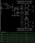
Here is a more complete schematic of my method in post #2. Unfortunately I have not found a way to obtain smoothly variable 1-99 percent duty cycle.

one D FF then OR NOR gates distrib pulses comprehensive.png

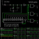
Here is a method where a 4017 decade counter distributes pulses to 3 outputs. The plain logic gates can be replaced with SR flip-flops, allowing more options to make use of the 4017 outputs. It becomes necessary to select a particular On-Off sequence.

4017 dec ctr distrib adjustable pulses to 3 NAND gates 67-99pct.png

- - - Updated - - -

Duty cycle for all outputs can be set by adjusting a single potentiometer, which stretches or shortens discharge rate of a capacitor.
 
  • Like
Reactions: David_ and d123

    d123

    Points: 2
    Helpful Answer Positive Rating

    David_

    Points: 2
    Helpful Answer Positive Rating
Hello David___

I have a surprise for you...a Multi phase buckboost...attached
 

Attachments

  • LT3791fb_Parallel buckboost.pdf
    1.1 MB · Views: 163
Status
Not open for further replies.

Similar threads

Part and Inventory Search

Welcome to EDABoard.com

Sponsor

Back
Top