Continue to Site

Welcome to EDAboard.com

Welcome to our site! EDAboard.com is an international Electronics Discussion Forum focused on EDA software, circuits, schematics, books, theory, papers, asic, pld, 8051, DSP, Network, RF, Analog Design, PCB, Service Manuals... and a whole lot more! To participate you need to register. Registration is free. Click here to register now.

Digitally adjustable LV2576 - not working

Status
Not open for further replies.

boylesg

Advanced Member level 4
Joined
Jul 15, 2012
Messages
1,023
Helped
5
Reputation
10
Reaction score
6
Trophy points
1,318
Location
Epping, Victoria, Australia
Activity points
11,697
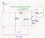
I have the following LM2576 circuit soldered.

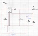
Adjusting R1 (pot) successfully on my soldered circuit successfully changes the output voltage according to my multimeter.
And I have adjusted this pot so that the output voltage is just on the 12V.
Q1 is supposed to short out the pot and reduce the voltage out put of the LM2576 but it has absolutely no effect regardless if I connect the base to 5V or GND, and I don't understand why not.
I copied the idea from a LM317 circuit that was using a similar method.

Is there anyway at all that I can digitally control the output voltage of LM2756 through PWM from an Atmega328 controlled TLC5940?
I am at a loss of how to achieve this with LM2576.


The component labelled LM2576 is not actually a LM2576 but rather a generic buck converter that I used because it had a similar pin arrangement to LM2576.

I used it just for the purpose of being able to show a schematic
LM2576.jpg
 

Attachments

  • LM2576.jpg
    LM2576.jpg
    95.9 KB · Views: 193
  • LM2576.jpg
    LM2576.jpg
    132 KB · Views: 174

Hi,

Q1 is not involved in the feedback circuit at all.
It just controls the load current.

And if you see no change in the output voltage, that just means that the buck controller works perfectly.

Klaus

- - - Updated - - -

Added:
For further discussion please give each of your schematics a "name" which we can refer to.
 

I copied the idea from a LM317 circuit that was using a similar method.
May be slightly similar, but surely quite different. You don't want to short the voltage regulator output but change the feedback resistor ratio. "Impossible" BC556 configuration in any case.

- - - Updated - - -

Provided you have a voltage regulator in adjustable configuration with resistor divider, the you can inject a DC current into the voltage reference node to shift the set point (or sum a voltage through a third resistor). If you derive the variable DC current or voltage from a PWM signal, a low pass filter is required to form a clean DC signal.
 

Hi,

with resistor divider, the you can inject a DC current into the voltage reference node
I agree.
Just to clarify:
With your circuit you don't need a true current source, because the sum_node has constant voltage (= feedback pin voltage).
A variable DC voltage (maybe generated by a low pass filtered PWM) and a resistor does the job.

Klaus
 

Hi,

Q1 is not involved in the feedback circuit at all.
It just controls the load current.

And if you see no change in the output voltage, that just means that the buck controller works perfectly.

Klaus

- - - Updated - - -

Added:
For further discussion please give each of your schematics a "name" which we can refer to.

Sort of dawned on me what was going on. I tried connecting the bottom of R3 to the feedback terminal to short out only R1 but then I get about 9V out regardless of where I connect the base of q1 - no better.

I give up with that scheme - it just doesn't work. Should of checked on my bread board rather than having faith that some one else's scheme would work.

Trying a different tack but having trouble understanding what is going on.

Ignore the the label of the Q2 in the schematic - it is IRLZ44N (5V logic level FET)....on my bread board.

The first schematic fails to turn on the LED. I measures a voltage of about 2V at collector of Q1 - not enough to turn on Q2. And I don't get where the rest of Vcc is being dropped.

FET1.jpg

The second schematic works fine switching the LED on and off. But it is inverting the logic.

FET2.jpg

Ultimately the base of Q1 will be connected to a channel of TLC5940 and the LED will be replaced with the input power of a EL wire driver, i.e. the aim is to vary the voltage input to the EL wire driver and therefore vary the intensity of the EL wire.

I guess given the above, inverting the logic doesn't really matter. But I would still like to know why the first schematic does not work as I assumed it would.
 

Hi,

I tried connecting the bottom of R3 to the feedback terminal
I'm not sure if you realized the mistake:
You didn't connect R3 or Q1 to the feedback node...you connected it to the output node, and thus it doesn't modify the output voltage.

--> Connect Q1 to the feedback node and it will work.

Klaus
 

Hi,


I'm not sure if you realized the mistake:
You didn't connect R3 or Q1 to the feedback node...you connected it to the output node, and thus it doesn't modify the output voltage.

--> Connect Q1 to the feedback node and it will work.

Klaus

There is no LM2576 in Multisim....at least not that I can find.

I simply used a convenient other component with 5 similar pins just for the purpose of providing a schematic.

Don't assume that this schematic exactly matches the real circuit I am working with.

The circuit I haves used is the same as in the schematic, as detailed in the LM2576 data sheet, with a real LM2576 in place of that convenient Multisim component with 5 similar pins and I do have the middle of the voltage diviers connected to the feedback pin in my real circuit.
 

Let's try this a different way - vary voltage to EL control circuit using an Arduino

How can I do this?

Trying to control the voltage output of an LM2576 does not work....from the other thread.

7 x EL wires colours and 7 x driver modules.

6 x PWM pins on an atmega328.

So TLC5940 is the only option.

How can I put 12V on the drain of a logic FET, connect the N-FET source to the + of the EL wire driver module, the - of the EL wire of the EL driver module to GND and then use the PWM on the TLC5940 channel to vary the voltage supplied to the EL wire driver modules?

My idea was to have the TLC5940 drive BC557s and then have these drive the N-FET gates.
 
Last edited by a moderator:

I would expect a schematic where the voltage feedback is varied by a control signal, but so far I haven't seen any in this thread.
 

I would expect a schematic where the voltage feedback is varied by a control signal, but so far I haven't seen any in this thread.

Please see post number 5 for latest schematic. Again Multisim is limiting in that it does not have the FET I am actually using. So please assume that my real circuit is using a IRL44N.

The switch I have in the schematic will be a PWM signal from a TLC5940.

I am just trying to understand why the BC556 successfully turns on the IRLZ44N in one configuration but not the other.

Should be a very straight forward question for you experts.
 

I miss to understand how the post #5 schematic should be related to adjusting a voltage regulator.

If the purpose is just turning the MOSFET on and off, neither of the circuits provides sufficient gate swing to turn the MOSFET fully on. Supplying the MOSFET drain form 12V is useless in so far. May it's not intended to switch the 12V to MOSFET source, but in this case we are missing a specification of circuit purpose.

You missed the bit where I said I had given up on the digitally controlled LM2576 idea because it just doesn't work and this seems to have been confirmed by multiple experts.

I am exploring this new idea to achieve my goal of digitally controlling the voltage supplied to an EL wire driver module.
 

Hi,

You missed the bit where I said I had given up on the digitally controlled LM2576 idea because it just doesn't work and this seems to have been confirmed by multiple experts.
No, what you say is not cirrect.
Digital feedback control does work,
But you made a mistake in your circuit, thus your circuit does not work.
Correct your circuit and it does work

Klaus
 

I fear the thread will lead to nothing. You are presenting different, apparently faulty circuit ideas without telling the circuit specification, e.g. intended voltage, current and timing.
 

Hi,


No, what you say is not cirrect.
Digital feedback control does work,
But you made a mistake in your circuit, thus your circuit does not work.
Correct your circuit and it does work

Klaus

OK would you mind showing me how to apply digital control over the output voltage based on the bog standard LM2856 schematic from the datasheet?

And I have found a far easier way to do this with massively fewer components.

Rumaging through my components, I remembered that I salvaged a bunch of 4 terminal low dropout (on/off) linear 12V regulators.

And these will work with the 5V from a TLC5940 channel.

And I have an old 20V laptop power supply.

Basically 3 components for each of the 7 EL wire controllers, in addition to the Atmega328 and TLC4950.
 

Hi,

Read post#2, read post#6.

Klaus
 

What's the EL driver current consumption at 12V supply voltage?
 

Hi,

Read post#2, read post#6.

Klaus

Klaus the schematic I showed you is improvised in Multisim because I cannot find an LM2576 component.

I used a 'stand in' device that happened to have 5 pins like the LM2576.

But I have no real idea what that device is nor the function of its pins, other than the obvious ones.

So I have probably connected the middle of the voltage divider to the wrong pin since I guessed the function of each pin.

My real soldered circuit is working just fine without the transistor and I can adjust the voltage by adjusting my trim pot, and I adjusted the pot to the point just before Vout starts falling below 12V

So just ignore the fact that my Multisim schematic is not entirely accurate.

I tried connecting the transistor (with a 120R resistor) from the Vout to the middle of the voltage divider in order to short out R2. (schematic from LM2576 datasheet)
However I seem to get a fixed 9V for Vout and it doesn't matter if I connect the transistor base to 5V, when I am expecting the voltage to fall below 12V since I have shorted out R2 (schematic from LM2576 datasheet).
 

I think it should be possible to sketch the real circuit, including the actual pwm control source. Presently we can say that the given circuit won't work.

Presumed the switch transistor would be connected correctly and the base controlled by a useful signal, you still have the problem that injecting a pwm signal into the feedback path gives unpredictable behavior. Instead you want to filter the pwm signal to get a DC current or voltage and superimpose it to the feedback path. Suggestions how to have been previously made.
 

Hi,

Klaus the schematic I showed you is improvised in Multisim because I cannot find an LM2576 component.

I used a 'stand in' device that happened to have 5 pins like the LM2576.

But I have no real idea what that device is nor the function of its pins, other than the obvious ones.
No need for a true LM2576 component.

The problem is not with the LM2576 component, but with your wrong wiring.

Sorry for repeating me:
--> Q1 in your circuit is obviously not connected to the feedback node. --> connect Q1 to the feedback node and it wil work.

So I have probably connected the middle of the voltage divider to the wrong pin since I guessed the function of each pin.
Please read the posts again.
Nobody said that your voltage divider wiring is wrong. Refer to the LM2576 datasheet.
--> It is correct. Don´t change the wiring.

I tried connecting the transistor (with a 120R resistor) from the Vout to the middle of the voltage divider in order to short out R2. (schematic from LM2576 datasheet)
Yes, as already written. You need to disconnect Q1 from VOUT and connect it to the feedback path = middle of the voltage divider.

Whil this will vary the output voltage ... I recommend to improve the circuit:
Use an NPN:
* Base via resistor to the microcontroller pin
* emmitter to GND
* collector via resistor to feedback.

With this circuit it´s more obvious what the transistor does. and resistor calculation is more simle:
When base is HIGH: the collector_resistor is in parallel to the lower voltage divider resistor --> increasing the output voltage.
When base is LOW: only the two voltage divider resistors control the output voltage
This is a two step ouptut voltage control.

****
For linear ouptut voltage control I usually don´t use a transistor.
I just use:
R10 in series with R11 from AVR_PWM_pin to LM2576_feedback
C10 from center (R10, R11) to GND.
Let´s say R10 = R11.

The change in output voltage is:
delta_v_out = (V_FB - dutyCycle x Vcc_AVR) * R1 / (R10 + R11)

Choose C10 to get low ripple: The higher the value the less ripple, but the slower the reaction on PWM_changes.

Klaus
 

Status
Not open for further replies.

Part and Inventory Search

Welcome to EDABoard.com

Sponsor

Back
Top