Continue to Site

Welcome to EDAboard.com

Welcome to our site! EDAboard.com is an international Electronics Discussion Forum focused on EDA software, circuits, schematics, books, theory, papers, asic, pld, 8051, DSP, Network, RF, Analog Design, PCB, Service Manuals... and a whole lot more! To participate you need to register. Registration is free. Click here to register now.

PIC12F675 Changeover and High Voltage Detection

Status
Not open for further replies.

mcmsat13

Member level 5
Joined
Apr 24, 2013
Messages
94
Helped
4
Reputation
8
Reaction score
4
Trophy points
1,288
Activity points
2,287
Hello able engineers! Greetings to all!

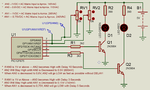
Please I need someone to code PIC12F675 with the description on the schematic provided below.

PLEASE THE PINS OF THE MCU CAN BE EXCHANGED TO ANY WAY IT WILL BE BETTER IF THE WAY I CHOSE THEM IS WRONG

I want to use this to interface with a device in my remote farm. I have two sources of Power supply there. I just want to use MCU because cost is insignificant. I just don't want to use analogue.

Thanks so much in advance.
 

Attachments

  • PIC12F675 Project.png
    PIC12F675 Project.png
    135.7 KB · Views: 344
  • PIC12F675 Project.rar
    144.4 KB · Views: 182

Hello all, please can't someone here offer to help me write this code?

Thanks for your cooperation!
 

Many of us can HELP YOU write the code, tell us how far you have gone so far. In terms of program complexity it is a very easy task to do.

Brian.
 

do you have a programmer to program the code?
I can write a program in ccs c for you.

albert
 
I have pickit3. I can program the IC by myself. Thanks.

- - - Updated - - -

The circuit is not complex. I will send the complete circuit now.

I can burn HEX onto Chips. I use MPLAB, PICAKIT3

- - - Updated - - -

PIC12F675 Project RL.jpg


This is what the MCU will control. It will switch off the relay driver during high voltage.

Thanks.
 
Is it a drawing fault or do you really want to connect the 100 µF capacitor in parallel to the relays coil?

It's not clear how the AC measurement is actually connected. What's the purpose of RV1 and RV2? Are they dummy sources for simulation?
 

The 100uf is drawing mistakes. The RV1 and RV 2 are simulation dummies.
 

I have pickit3. I can program the IC by myself. Thanks.

- - - Updated - - -

The circuit is not complex. I will send the complete circuit now.

I can burn HEX onto Chips. I use MPLAB, PICAKIT3

- - - Updated - - -

View attachment 146479


This is what the MCU will control. It will switch off the relay driver during high voltage.

Thanks.

I have written a program but have not tested it.
can you test this?

Greetings
albert

- - - Updated - - -

I have made some adjustments.
can you test this?

Greetings
albert
 

Attachments

  • PIC12F675 Changeover and High Voltage Detection.rar
    18.5 KB · Views: 139
  • PIC12F675 Changeover and High Voltage Detectiont.rar
    20.7 KB · Views: 139

I have not tried the code but I'm a bit skeptical about a few aspects of it.
Firstly, there are only 64 bytes of data memory and you use 42 of them in the main C file. Are any used in the library functions that are called?
Further, the device as 1K words for the program and you are using floating point calculations. The HEX file shows addresses up to 0x4d5 but the program address space on that chip only goes to 0x3ff so I doubt if it will fit.
I see references to RTCC- the target device does not have an RTCC and the OP has not included one is the design. Going by the CCS User Manual, this uses 'Timer0' which is an 8-bit timer. However you initialise the count to 'HIGH_START' which is defined to be "0xFFFF - 500" - i.e. a 16 bit value.
You have effectively written a state machine to handle when the LEDs are to turn on and off - this is a very reasonable way to go about this task. However there are variables with names such as 'delay_3sec', 'delay_5sec' that are set to false as part of the initialisation, then set to true in the ISR and tested in the main loop. FOr a start, such variables should be declared as 'volatile' so the compiler will force a read of the variable outside the main loop. However the real problem is that these variables are never set to false.
I'm only too happy to be proved wrong, but I don't think you are really helping the OP. It is far better for them to learn how to program the device themselves than to be given (in my opinion) poorly written code to use as an example that must be significantly re-written to make fit in the MCU, let alone made to work.
Susan
 

Further, the device as 1K words for the program and you are using floating point calculations. The HEX file shows addresses up to 0x4d5 but the program address space on that chip only goes to 0x3ff so I doubt if it will fit.
That's OK. Processor has 1k words, hex address counts bytes. CCS C would never compile the code if it doesn't fit the processor flash.

As far as I see, you are right about Timer0 frequency. Needs correction.

However there are variables with names such as 'delay_3sec', 'delay_5sec' that are set to false as part of the initialisation, then set to true in the ISR and tested in the main loop. For a start, such variables should be declared as 'volatile' so the compiler will force a read of the variable outside the main loop. However the real problem is that these variables are never set to false.
The flag variables are reset in the main code. They should be declared volatile, but CCS C never optimizes code in a way that volatile takes effect. Porting the code to other compilers may require it, depending on the optimization settings. Bit flags can be declared as int1 in CCS C to save code and data space, by the way.

The most questionable point in my view is the usage of float for quantities that have only 10 bit resolution (and even less accuracy). As no calculation with ADC values takes place, you can use them directly with pre-calculated integer threshold values.

Finally, to correct a popular fault, the ideal ADC LSB is Vref/1024 rather than Vref/1023, review PIC family reference manual.

- - - Updated - - -

Getting rid of float usage reduces resource utilization to 27% ROM and 39% RAM.
 

I have not tried the code but I'm a bit skeptical about a few aspects of it.
Firstly, there are only 64 bytes of data memory and you use 42 of them in the main C file. Are any used in the library functions that are called?
Further, the device as 1K words for the program and you are using floating point calculations. The HEX file shows addresses up to 0x4d5 but the program address space on that chip only goes to 0x3ff so I doubt if it will fit.
I see references to RTCC- the target device does not have an RTCC and the OP has not included one is the design. Going by the CCS User Manual, this uses 'Timer0' which is an 8-bit timer. However you initialise the count to 'HIGH_START' which is defined to be "0xFFFF - 500" - i.e. a 16 bit value.
You have effectively written a state machine to handle when the LEDs are to turn on and off - this is a very reasonable way to go about this task. However there are variables with names such as 'delay_3sec', 'delay_5sec' that are set to false as part of the initialisation, then set to true in the ISR and tested in the main loop. FOr a start, such variables should be declared as 'volatile' so the compiler will force a read of the variable outside the main loop. However the real problem is that these variables are never set to false.
I'm only too happy to be proved wrong, but I don't think you are really helping the OP. It is far better for them to learn how to program the device themselves than to be given (in my opinion) poorly written code to use as an example that must be significantly re-written to make fit in the MCU, let alone made to work.
Susan


ok I have been a bit sloppy, the timer is indeed only 8 bit, I wrote this code in 15 min and still needs to be adjusted but I wanted to post it to start a reaction.
ok then we make 500us instead of 1ms
I know that the Start_delay_3sec and Start_delay_5sec are not being reset, but I still had to have additional information about the correct circumstances of the intention.

I planned to ask these questions today.
for example:
"if AN0 is 1V or above --- AN2 becomes High with Delay 10 Seconds"
does AN0 have to stay above 1V during these 10 Seconds?
if AN0 is below 1V during these 10 seconds, should the time start again? .. etc.
same question for AN1 and AN3

I use floting because it is easy to detect a voltage of 0.6 and 0.75 and it is not timeless anyway


the ccs compiler uses automatic timer0 when you put int_rtcc in your code.

if you look in the .lst file you will see that there is enough space and that timer0 is used.

there is more than enough memory (what are you going to do with the surplus?)

and as FvM says ADC LSB is Vref / 1024 rather than Vref / 1023

I have added a control LED that every second toggled (gp5)
I loaded the code and the LED blinked 1sec on 1sec off.
resetting of the flags has not yet been adjusted because additional information is needed for this.

the code is not optimal, but is that important?
 

Attachments

  • PIC12F675 Changeover and High Voltage Detection_v1_Led.rar
    23.1 KB · Views: 119
Last edited:

I'm sorry for my late reply. I traveled to a remote village yesterday and got delayed there. I only had my mobile phone Internet there and unfortunately my battery ran out!

"I planned to ask these questions today.
for example:
"if AN0 is 1V or above --- AN2 becomes High with Delay 10 Seconds"
does AN0 have to stay above 1V during these 10 Seconds?
if AN0 is below 1V during these 10 seconds, should the time start again? .. etc.
same question for AN1 and AN3"

If AN0 happens to go below 1V during this 10 seconds delay, the MCU will ignore it. Before AN2 becomes high, the AN0 must remain 1V or above during the 10 seconds delay. The same thing applies to the AN1 and AN3.

- - - Updated - - -

I will check this code out.

Thanks.
 

Hi,

Feel glad that someone else does your job or homework - without pay.
This is not how a forum is meant to work. But it's not a problem, either.

"I planned to ask these questions today.
for example:
"if AN0 is 1V or above --- AN2 becomes High with Delay 10 Seconds"
does AN0 have to stay above 1V during these 10 Seconds?

That's interesting. You are the designer, but you ask the software-writer how it should work?
In my eyes this clearly is your job to give the software designer a good, unambiguous description (specification).

Klaus
 

See Sir, I do some electronics hobby. Electronics is my fun. I always want to know but I am limited to analogue electronics. I have been reading about electronics and love MCUs and how they operate but writing their codes remains a wonderment to me.

I want to use this to replace a changeover in one and ancient Inverter I got at a factory junk.

I have not seen such an old thing, neither have I seen such thing which is engraved on the back "Made in Turkey"! Well I already have an Inverter in my house I still take this device as an antique. It's having a Changeover problem. I put it in my grandma house and I found out that if there's a high voltage or low voltage, it misbehave. And it doesn't have protections for these. It's not that I can't accomplish this task with analogue electronics but I fancy MCU and look at the people who can write their codes with high interest and so much regards.

- - - Updated - - -

Please Moderator, I personally beg you now to help me write this code. I strongly believe you can do it, Sir!

- - - Updated - - -

Moderator... I mean Moderator Klaus.

- - - Updated - - -

Please Moderator Klaus, you are like our father here... Please help your Children

- - - Updated - - -

Please Moderator Klaus, you are like our father here... Please help your Children
 

So good they say it twice!
Please Moderator Klaus, you are like our father here... Please help your Children
Well Klaus, I think you just got nominated to be a UNICEF ambassador :-D

mcmsat13, what would really help here is a graph, it doesn't need to be very accurate or to scale, showing time along the horizontal axis and the analog and digital outputs on the vertical axis so we can see the sequence of events you want to create. What we are not clear about is what happens if for example, AN0 goes high and low straight away, does it still turn the LED on for 10 seconds? You have only described some of the conditions but we need to know how it should react for all combinations of inputs.

Brian.
 

I'm not so deep in electronics as you Sir.

As you asked, if AN0 goes high or low straight away, well, I never knew that this will stretch like this. Nevertheless, I also learn from these comments.

If I may say:
If AN0 is high >1v and 10 seconds elapsed, AN1 will go high, and stay high unless AN0 is below <0.6v.

AN0 and AN2 will work independently
Remember, even at the high voltage detection by AN2 only that Transistor Q1 would have been turned off by AN3 Q2.
This means that the relay is off.
 

OK, let me ask more questions:

1. Do you mean that AN0 must stay >1V for 10 seconds continuously, then AN2 goes high?
2. If AN0 drops to any voltage >0.6V AN2 stays high?
3. If AN0 drops <0.6V, AN2 immediately goes low and stays low unless condition 1 is met again?

4. If AN1 stays >1V for 3 seconds continuously, then AN3 goes high?
5. If AN1 drops to any voltage >0.75V AN3 stays high?
6. If AN1 drops <0.75V for 5 seconds continuously, AN3 immediately goes low and stays low unless condition 4 is met again?

Incidentally, when referring to analog inputs we use the 'ANx' name for the pin but if the pin is configured as an output we use it's other name "GPx'. So when you say AN2 it should really be GP2 and instead of AN1 you should say GP4.

Brian.
 

I have modified and tested the program.

I have added a TestPin.

Pin 4 (GP3 / MCLR) must be connected with 10k to + (VDD) becomes TestPin.
Normal operation TestPin open Led flicker with cadence of 1 sec.
When TestPin is connected to GND, Led will flash quickly, the delay will be practically disabled. u You can test the level with the potentiometers.


ROM used: 738 words (72%)
Largest free fragment is 286
RAM used: 36 (56%) at main() level
53 (83%) worst case
Stack: 3 worst case (2 in main + 1 for interrupts)
 

Attachments

  • PIC12F675 Changeover and High Voltage Detection_v1_Led&test.rar
    24.5 KB · Views: 128
@ Brian That is just what I want!

"1. Do you mean that AN0 must stay >1V for 10 seconds continuously, then AN2 goes high?
2. If AN0 drops to any voltage >0.6V AN2 stays high?
3. If AN0 drops <0.6V, AN2 immediately goes low and stays low unless condition 1 is met again?

4. If AN1 stays >1V for 3 seconds continuously, then AN3 goes high?
5. If AN1 drops to any voltage >0.75V AN3 stays high?
6. If AN1 drops <0.75V for 5 seconds continuously, AN3 immediately goes low and stays low unless condition 4 is met again?

Incidentally, when referring to analog inputs we use the 'ANx' name for the pin but if the pin is configured as an output we use it's other name "GPx'. So when you say AN2 it should really be GP2 and instead of AN1 you should say GP4.

Brian."

Right! The question is just the answer!

Thanks.
 

I have modified and tested the program.

I have added a TestPin.

Pin 4 (GP3 / MCLR) must be connected with 10k to + (VDD) becomes TestPin.
Normal operation TestPin open Led flicker with cadence of 1 sec.
When TestPin is connected to GND, Led will flash quickly, the delay will be practically disabled. u You can test the level with the potentiometers.


ROM used: 738 words (72%)
Largest free fragment is 286
RAM used: 36 (56%) at main() level
53 (83%) worst case
Stack: 3 worst case (2 in main + 1 for interrupts)

@ arexxx, you are a great friend. This code works fine. You just did a great work here. You really are in this stuff.
 

Status
Not open for further replies.

Similar threads

Part and Inventory Search

Welcome to EDABoard.com

Sponsor

Back
Top