rafakath_aimil
Newbie level 5
Sir,
I am working on Pulsar circuit which will drive ultrasonic transducer. I need to exit transducer at 600v to 800v, but pulsar circuit provide 400v max. even if VDD is 600v. What could be the resion for voltage drop kindly suggest.
Attach circuit diagram.
I have experiment by changing R and C value.
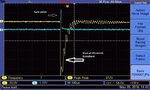
Excitation Pulse duration is 10uSec at a frequency of 50mSec is applied to MOSFET gate.

I am working on Pulsar circuit which will drive ultrasonic transducer. I need to exit transducer at 600v to 800v, but pulsar circuit provide 400v max. even if VDD is 600v. What could be the resion for voltage drop kindly suggest.
Attach circuit diagram.
I have experiment by changing R and C value.
Excitation Pulse duration is 10uSec at a frequency of 50mSec is applied to MOSFET gate.
Last edited by a moderator: