Continue to Site

Welcome to EDAboard.com

Welcome to our site! EDAboard.com is an international Electronics Discussion Forum focused on EDA software, circuits, schematics, books, theory, papers, asic, pld, 8051, DSP, Network, RF, Analog Design, PCB, Service Manuals... and a whole lot more! To participate you need to register. Registration is free. Click here to register now.

[SOLVED] Laptop Webcam to Micro USB

Status
Not open for further replies.

Thayne

Member level 3
Joined
Apr 28, 2018
Messages
60
Helped
1
Reputation
2
Reaction score
1
Trophy points
8
Activity points
637
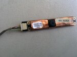
I want to attach a webcam taken from a laptop to a phone and use this "USB camera" app to use the phone as a display for the webcam. (I am making an endoscope for my wife's work as a biologist.)

So, there are five wires at both ends of the removable cable that plugged the webcam to the laptop (via plastic connectors). I cut open a few USB cords and the color coding does not match up. I looked up the pinouts to wire Standard USB pinout (Type A) and micro USB (micro-B), but nothing is matching color-wise, or in connector positions.

Please help.

Thanks in advance!

IMG_20180424_134935.jpg

IMG_20180424_134935.jpg
 

Attachments

  • IMG_20180424_134942.jpg
    IMG_20180424_134942.jpg
    494.2 KB · Views: 875

You first need to find out whether the laptop actually used USB internally to connect to the webcam, it is quite possible, being inside the laptop body, that some other interface was used.

I'm not sure how you can tell if your laptop used Windows but if you can boot Linux (any type) and type 'lsusb' (LiSt USB) at a command prompt it will tell you if it is a USB device and some information about it. If it doesn't appear in the list of USB devices you will never get it to work plugged into a USB port.

If it is USB, ignore the wiring colors as manufacturers are under no obligation to use a standard, especially if internal to another device. The ground connection will almost certainly be joined to the copper around the screw mounting holes (probably the thick black wire) and the twisted ones will be the data+ and data- wires. The red is probably the +5V connection but USB only needs four wires so what the fifth does is unknown. You might have to reverse the data wires and try it again as there is no easy way to tell which way around they should be.

Brian.
 

OK, I tested the continuity from the black wire (thicker one) to the copper on the board (the screw mounting holes) -- found ground there.

I also tested the continuity from the yellowish/green wire to the copper on the board (the screw mounting holes) -- found ground there too.

The other wires have no continuity to the mounting holes.

So far then:

Black (larger gauge) - Ground
Green (Yellowish) - Ground
Black - Data
White - Data
Red - +5 Volts?

So, what is the best way to test the black, red and white wires without frying anything? Should I test going to a computer, or to a phone?

Thank you!
 

The white and black wires are twisted so they will be the data wires, the red must be the 5V line. I would connect it to a computer first and see if you get a message announcing a USB device has been plugged in. If it doesn't work, swap the black and white wires and try again. You will only get a message if the wiring combination is correct.

I would guess the reason for two grounds is that one is the normal USB negative supply and the other is the shield around the cable.

Brian.
 

Thanks betwixt! Those were all the right wires. I hooked it up to my computer and it worked perfectly. Unfortunately, I cannot get any mobile phones to recognize it. I tried a number of apps too, but none work.

This may be related to why it won't work with the phones... When I plug the USB cam (Bison Cam) into USB 3.0 and 3.1, it is detected, but not recognized. Though, I have two USB 2.0 ports and it works perfectly with both of those. So, I will have to wire the camera to hook to a computer via USB, which isn't ideal (the mobility was important).

Thanks!
 

USB devices have descriptor tables in them that are read when the device is plugged in. It gives the host some idea of what it is and which driver software is needed. I would guess as your phone probably has a camera of it's own, the OS writers left other drivers out of the firmware.

Brian.
 

I presume, the mobile phone OS doesn't block the camera, but has no generic driver for it. There are e.g. the FLIR thermal imaging modules for Android phones connecting through USB.

You need to find a suitable app - or write it yourself.
 

There are a lot of camera apps for Android that do what I need. But, none of them work for me. Some are camera specific and many others are generic. I tried all the non-camera specific, generic apps (available in the Google Play store). Nothing. Maybe there is another outside the store...

I would like to write my own, but the only language I know is Fortran. LOL.

Thanks!
 

A USB driver in FORTRAN, does your phone have a slot for Hollerith cards?

Android is based on Linux, if you can access the root filing system it might be possible to copy a suitable Linux driver to the phone. I suggest if you don't already use Linux, download a 'live' version to USB or DVD and boot a PC from it. If you are using Windows, just say 'Try' (not 'install') when it asks, it will not touch any of your existing files and it you remove it and boot again the computer will be unaware of what you did. Then plug the webcam in and note which driver file it installs, copy that file to the phone. No guarantee it will work but there is a reasonable chance.

Brian.
 

I finished this thing the other day. It works very well. Thanks for all the help. On to the next project.

IMG_20180503_103922.jpg

IMG_20180503_103830.jpg
 

Status
Not open for further replies.

Part and Inventory Search

Welcome to EDABoard.com

Sponsor

Back
Top