Continue to Site

Welcome to EDAboard.com

Welcome to our site! EDAboard.com is an international Electronics Discussion Forum focused on EDA software, circuits, schematics, books, theory, papers, asic, pld, 8051, DSP, Network, RF, Analog Design, PCB, Service Manuals... and a whole lot more! To participate you need to register. Registration is free. Click here to register now.

auto reset pic 18f2550

Status
Not open for further replies.

erchiu

Member level 5
Joined
Apr 7, 2012
Messages
93
Helped
2
Reputation
4
Reaction score
1
Trophy points
1,288
Location
Rome - Italy
Activity points
2,082
hi everybody
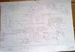
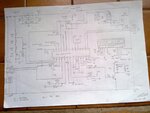
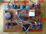
i am making an circuit for check the capacity of lead batteries and i used an pic18f2550.

for to check the capacity of the battery i connect to it an load and measured the current and voltage.

for make this i use an 5v relais.

but here i have a problem.

i maked the circuit in way that it can work in two different way.

first way :with external 5v power supply way usb
second way: directally from the battery by to check.

when i use the circuit in first mode (with an external 5v power supply), it work is good.

when i use the circuit in second mode (directally from the battery to check, the pic is reset when the load to discharge the battery is connected.
as can i solve this problem?
erchiu
 

To be clear, does the PIC reset as soon as the battery load is applied or does it take a little time (i.e. for the battery to discharge below a certain voltage)?
Also what do you mean by 'reset' - does it actually reset and then start working again, or does it stop working altogether?
Also a schematic might be valuable to see what is happening when the supply is from the battery.
Susan
 

Hi,

Without seeing your design it's impossible to give any valid answer.
All we can do is guess - and that's not how an engineer wants to work.

--> show us your design:
* schematic
* PCB layout
* photo of wiring
* code

My guess: EMC
Read about EMC problems. There are many threads here. A prper schematic and a proper PCB layout is the key to success.

Klaus
 

To be clear, does the PIC reset as soon as the battery load is applied or does it take a little time (i.e. for the battery to discharge below a certain voltage)?
Also what do you mean by 'reset' - does it actually reset and then start working again, or does it stop working altogether?
Also a schematic might be valuable to see what is happening when the supply is from the battery.
Susan

hi,
i think that it deals of the reset, because the problem happens in the moment the relais and the load is connected.
the battery that i try is very good and the problem is not certainly its voltage

the circuit and code work so.

when i press the start button, the relais connect the load to battery.

exactly in this moment the pic turn off and after it immediately it comes back on.

all this not happens if i drive the pic with another external power supply +5v (way usb port),
leaving the battery only for the load.

for the circuit i have only on paper sheet and think it not more understandable.
but if is necessary i can post it.
 

Attachments

  • IMG_20180423_095049.jpg
    IMG_20180423_095049.jpg
    534.9 KB · Views: 106

Battery is unable to power both load and PIC at the same time. Have you measured the total current requirement of your circuit ?
 

Yes, i have tryed with an battery that i know be good.
I not measured the current that require the circuit but i think is 70/80 mAh about.
you can see the picture?
is possible that the problem is the relais much near to the pic?
 

It's clearly the problem of current limit. When you applies load then it took all the current from battery and there's not much left for PIC Microcontroller. May be your load gets more current on startup like a spike.

I would recommend you to use a 2200uF or higher capacitor between your battery terminals, that will solve the issue.
 

Hi,

Battery is unable to power both load and PIC at the same time. Have you measured the total current requirement of your circuit ?
I don´t agree.

It's clearly the problem of current limit. When you applies load then it took all the current from battery and there's not much left for PIC Microcontroller.
I don´t agree.

It more relates to the voltage of the battery. I doubt it drops that much that the microcontroller refuses to work.

I still think this is an EMC issue. --> No GND plane, no filtered board_IOs, a couple of differnet devices connected to different potentials.

For sure this is just guessing, because we don´t see a schematic to verify. We don´t know the load current nor do we know what battery and what battery condition....

Klaus
 

Yes you are right, it's problem of voltage but it's caused because of current peak. Some devices on start up draws instantaneous peak current, which caused their voltage to drop, for example SIM900 module.

In order to provide this peak instantaneous current we have to use capacitor coz it stores charge, and can provide such current and will avoid the voltage drop.
 

Hi,

it's caused because of current peak. Some devices on start up draws instantaneous peak current, which caused their voltage to drop, for example SIM900 module.
Where do you know about:
* current or current peak
* voltage drop
* SIM900?

All I know is this:
when i press the start button, the relais connect the load to battery.
exactly in this moment the pic turn off and after it immediately it comes back on.
***********
I would recommend you to use a 2200uF or higher capacitor between your battery terminals, that will solve the issue.
Yes, let´s try.
I assume it will not solve the problem.

Klaus
 

Hi,

Don't take it personal :p Let me try to explain it again. Some loads have this characteristic that when they start then they need a lot of current but after that they for their normal operations they don't need much current. I have attached the image of such case and you can see in that image, at the start the current is quite high but after that it goes low. That's the exact case of SIM900 module, which I was talking about before. :)

So, I think our friend here (who started this thread), has similar kind of load attached to its battery, that's why when he turns ON his relays and the LOAD is ON then its system goes down. Because load needs instantaneous peak current which makes the system to fail but once the load is started then the system goes back normal and user gets its PIC restarted :p

That's why I have suggested to use capacitor, now this capacitor acts as a charge storing element and it can provide this peak current and can save the system. It's not necessary that it would work but it's worth trying. :)

Have a good day.

SIM900-power-consumption-initial-registration-and-location-update.png
 

I feel that the thread is pretty vague about the battery under test as well as the switched test load. Presently it's only a guess that the test load causes a voltage drop below PIC POR reset level. It could also be a problem of relay arcing causing a processor reset.

More generally, powering the processor from the battery under test can only work if the test load is small enough to keep sufficient supply voltage margin.

Connecting a bypass capacitor to the test object doesn't seem the right way, if at all, the capacitor should have an isolation diode to buffer only the processor supply but don't source current to the load resistor.
 

Hi,
Don't take it personal
No, I don´t.

Let´s focus on the OP´s informations.

* the aim is to build a circuit to measusre the capacitance of a lead battery. (It´s not to build a random battery operated circuit)
* for this he connects a load via the relay...and measure the load current and battery voltage to calculate battery capacity. (An unknown or unpredictable load current will make the design more difficult)
* "the battery that i try is very good and the problem is not certainly its voltage"
* we see that there already is an electrolytic capacitor near the power supply circuit.

And we see the circuit and how it is built. It is prone to have EMC problems.
Thus we need more detailed information about if and what techniqes are used to prevent the circuit to fail on EMC.
Schematic is essential for this... with device values..

Klaus
 

Yeah may be. Let's wait for the thread creator to reply and see what he got. :)
 

Hi everyone,
in these days i maked various tests.
Anyway i attacched the original circuit that i maked.
the load is a little led light from 5w and 12v.
i tryed to insert an 2200 uf capacitor on the battery, but not work.
i added an resistor 4k7 (respect to circuit) betwwen the base and emitter of npn, but nothing.
i put the diode on the pinout of pic that drive the load (pin11)., but nothing.
i added other 2 diodes 4148 on relais coil but nothing.
I wanted to remind you that the circuit work good when the pic is power supply externally way usb and the the battery used only for the load. In this case i tried also an major load (10w about 1Ah) and is ok.
I am sorry but for moment i have only this schematic maked with pencil.
Erchiu
 

Attachments

  • IMG_20180428_102240.jpg
    IMG_20180428_102240.jpg
    396.7 KB · Views: 103
  • 28042018585.jpg
    28042018585.jpg
    483.8 KB · Views: 88
Last edited:

Have you already carried out the test without connecting the load LED?
it is possible that the relay is the problem.
I always put a snubber circuit across the coil as well; either a self contained one, or a 10 Ohm resistor in series with a .22uF capacitor (for a 5VDC coil); again, for transient suppression.
when I see the photo of the print, I see that the USB connection is at the top left and the lm7805 at the bottom right.
the peak current in the relay (coil) is greater if the connections of the relay are shorter to the power supply, in this case the lm7805 is close to the relay and thus causes a larger EMC.
you can place a resistor of 1 to 10 ohms in series with the emitor of the switching transistor, which then limits the (peak) current. a snubber circuit across the coil is certainly needed if you do not use a separate power supply.
I would also place a decoupling of 100uf close to the 18f2550.
 

Status
Not open for further replies.

Similar threads

Part and Inventory Search

Welcome to EDABoard.com

Sponsor

Back
Top