Continue to Site

Welcome to EDAboard.com

Welcome to our site! EDAboard.com is an international Electronics Discussion Forum focused on EDA software, circuits, schematics, books, theory, papers, asic, pld, 8051, DSP, Network, RF, Analog Design, PCB, Service Manuals... and a whole lot more! To participate you need to register. Registration is free. Click here to register now.

Low low frequency square wave doubler 20Hz to 200Hz input

Status
Not open for further replies.

teliocide

Newbie level 4
Joined
Apr 22, 2018
Messages
7
Helped
1
Reputation
2
Reaction score
1
Trophy points
3
Activity points
74
I need to increase the frequency of a square wave signal by a factor of 2.
The source signal is in the range 20 to 200 Hz so the output will be 40-400Hz.
The source signal duty is less than 50%.
The available supply voltage is 14VDC
At this point in time I am unsure what the minimum acceptable duty on the output is.
I think the device receiving the doubled signal only requires a trigger signal.
I have a vague memory of people using logic gates for this.
All assistance greatly appreciated.
 

Hi,

The simplest solution may be to generate a one shot pulse on every input signal edge.

Other solutions are:
* microcontroller measuring the input frequency and generate an independent output frequency
* PLL
* completely digital solutions with a PLD and a high frequency system clock.

Klaus
 

Thanks,

Is it possible to point me in the direction of suitable circuit?

Greg
 

Hi,

Maybe take a look at some of the Google search results for frequency doubler circuit, then when you choose a circuit, doubts about the circuit of choice of whatever kind can be discussed further.

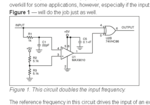
This is one of the results from a Maxim Integrated app note APP3327:

frequency doubler maxim.PNG

Simple Circuit Doubles Input Frequency
 

Thanks.
There are a few circuits around but most are set up for MHz and GHz.
Getting the components changed to make the circuit operate at 20-200Hz has been a failure due to my skill set and or lack of.
This one has appeal as it is described as capable of operating over a broad input frequency range.
The configuration shown in the image is for 500+Khz
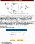
slow 4069.jpg
 
Hi,

Adjusting the frequency is simple:

If you want to adjust for a 1/1000 of the frequency use 1000 times the capacitance value.

Klaus
 

Thanks,
Using your thousand factor I have come up with this.

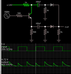
Slowed down.jpg
 

Why not check the circuit operation in a simulation, or build it on a bread board and watch the waveforms?

The circuit is generating constant pulse width, a requirement is to have still separated pulses at 200 Hz, thus pulse width must be in any case smaller than 2.5 ms, e.g. 2 ms.

The lower limit is set by the minimal pulse width accepted by the driven circuit, did you check in the meantime?
 

"The lower limit is set by the minimal pulse width accepted by the driven circuit, did you check in the meantime?"
This I understand but at this point it time do not know the answer. It is a major task the get this info.
I know the minimum frequency accepted by the driven circuit but not the minimum duty.

It is my strong intention to build it as I need it.

My background is in Microbiology, Genetics, Biophysics and Hydrology ......my tiny wee electronics is from necessity not from formal training.
Therefore I must doubt every direction I take.
So before I waste my time and solder together total crap it is better if I run my ideas past the experts.
I do not have simulation software...... however I can solder stuff together and have had reasonable success over the past 50 years.
Basically i am asking if the component values are correct. You gentle-persons should be able to spot garbage at a 100m.
If I write garbage it is your duty to point this out without hesitation.
 

Hi

I´m confused: If there is a calculator, then wy didn´t you use it before?
****

With my calcuation you don´t have to change the resistor values. Only the capacitor values.

Klaus
 

I never new the calculator existed
I guessed something like it may exist after you informed me of x1000 rule....... so I googled "frequency + capacitance x 1000"

Forgive my ignorance, but the the resistor control the rate of charge of the capacitor????? So there must be an ideal value for the resistance to match the capacitors reactance and the circuit frequency ?????
 

Hi,

You Tau = R x C.

To modify Tau you may modify R, or you may modify C, but if you want it the difficult way you may modify both.
I see no benefit in changing both. There is no ideal resistor value.

Klaus
 

I found a NE555 circuit for this. Nice design as the duty cycle could be controlled. But this only worked at set frequency +- a few Hz.

I need to pursue the 4069 circuit at the top of this post.
So I have dived into LTSPICE.

Unfortunately I cannot find a 4069 model for LTSpice so I cant test in the virtual ethers of a Windows black box.

Where can I get a 4069 model for ltspice?

Thanks
 

Hi,

One option is to look at one or several manufacturers' websites on the actual product page and check if there isn't a model version or several to choose from you can use. I use Tina-TI, the models I add from them and other manufacturers are often PSpice versions already but for some reason I'd thought they were valid for LTSpice too, maybe I'm wrong on that one as I haven't tried.

If you need to and want to try, there's a way of converting PSpice models to LTSpice. I don't know if it's a procedure which is hard or easy to follow. It looked relatively simple with only a few steps once you get the hang of it. Analog Devices have an online tutorial/app note about it. It's such a common device there must be several models.

A relatively longer approach if you don't find a model would be to join TI, download the free TINA version, and use the ready made model of the 4069, or the model of the 4049. It also has the model for the SN7404, TTL but still could be of interest. To simulate oscillators on the free version you sometimes need to change three analysis parameters - should you ever want them, let me know and I'll upload the relevant info I found to save having to search yourself.

Hope you found a model, anyway.
 

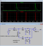
For the scope of this question, you can use Ltspice digital gates with a logic level of 12V and additional diodes modelling the substrate diode clamping effect.

The circuit is simplified by using a NOR gate. NOR gates gates can also replace the inverter, making the circuit with a single CD4001.

freqdoubler.PNG
 

Attachments

  • freqdoubler.zip
    1 KB · Views: 57

A CD4047 has a variable frequency oscillator and a divide by two circuit with two opposing outputs.
If you want to double the frequency of another generator then let its output be Cmos levels and feed it into pin 3 of the CD4047.
 

Status
Not open for further replies.

Part and Inventory Search

Welcome to EDABoard.com

Sponsor

Back
Top