Continue to Site

Welcome to EDAboard.com

Welcome to our site! EDAboard.com is an international Electronics Discussion Forum focused on EDA software, circuits, schematics, books, theory, papers, asic, pld, 8051, DSP, Network, RF, Analog Design, PCB, Service Manuals... and a whole lot more! To participate you need to register. Registration is free. Click here to register now.

[SOLVED] What is the best software to simulate a boost converter with current control?

Status
Not open for further replies.

tarikelec

Member level 2
Joined
Nov 22, 2017
Messages
48
Helped
0
Reputation
0
Reaction score
0
Trophy points
6
Activity points
524
What are the best software to simulate a boost converter with current control ?

hello everyone,

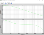
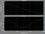
I have designed a boost converter with peak current mode control and I wanted to evaluate the transfer function in bode plot of the Verr to Vout as you can see in the files added the boost converter gives a bode plot without a DC gain meanwhile in the figure added you can see the DC gain when I use the math transfer function and use Matlab to get the bode plot.

I would love to know what I have missed getting the DC gain as the shape of the bode plot is good.?

thank you
 

Attachments

  • boost.zip
    59.3 KB · Views: 124

start a design of boost converter in cadence virtuoso?

Hello guys,
as I am new to cadence virtuoso, i have been asked t design a boost converter with peak current control mode in cadence virtuoso, what do you think, can I learn easily the cadence_virtuoso so I can use it to design my boost or will it take me too long. do you have any tutorials related to my design. I have designed my boost in simulink but I believe cadence virtuoso is another world.
any suggestion is welcome and thank you in advance
 

what are the best software to simulate a boost converter with current control ?

hello dears,
I have simulated my boost converter with peak current mode control in simulink/plecs and I could not successfully get the DC gain of my bode plot, So I have to find another simulation tools where I can simulate my design and get the bode plot of it.

thank you
 

Re: what are the best software to simulate a boost converter with current control ?

Plecs is quite intuitive, but as any simulation tool, has a learning curve. If you don't manage to measure loop gain in your Plecs simulation, what make you think that it's easier with a SPICE tool?

Actually, you didn't set up the loop meter correctly in your Plecs model. It already includes the perturbation source, you don't want a second perturbation source in the design. You also need to select the correct perturbation and response type in the analysis options.

The result should look like below:

loop gain.PNG

By nature, the tool can't measure DC gain. But it's almost pointless to measure the DC gain of a PI control loop with ideal integrator. It can be hardly smaller than infinity. If you don't believe it, vary the set point by a small delta amount and watch the output error.
 
  • Like
Reactions: CataM

    CataM

    Points: 2
    Helpful Answer Positive Rating
Re: what are the best software to simulate a boost converter with current control ?

Actually, you didn't set up the loop meter correctly in your Plecs model. It already includes the perturbation source, you don't want a second perturbation source in the design. You also need to select the correct perturbation and response type in the analysis options.
It works as you say, but also works keeping them, quote from the manual:
Perturbation
The Small Signal Perturbation block that will be active during the analysis.All other perturbations blocks will output 0.

Keeping the perturbations but setting the setup for Loop Gain measurement, gives the same result.

The one that the OP is not able to perform is Vout/Verror.
 
Last edited:

Re: what are the best software to simulate a boost converter with current control ?

Plecs is quite intuitive, but as any simulation tool, has a learning curve. If you don't manage to measure loop gain in your Plecs simulation, what make you think that it's easier with a SPICE tool?

Actually, you didn't set up the loop meter correctly in your Plecs model. It already includes the perturbation source, you don't want a second perturbation source in the design. You also need to select the correct perturbation and response type in the analysis options.

The result should look like below:

View attachment 146104

By nature, the tool can't measure DC gain. But it's almost pointless to measure the DC gain of a PI control loop with ideal integrator. It can be hardly smaller than infinity. If you don't believe it, vary the set point by a small delta amount and watch the output error.

FVM out of curiosity what type of loop is that. That looks like a modified PI (two pole one zero) with a pole-pole-zero configuration as opposed to the more typical pole-zero-pole. Is that correct?

I ask because I've designed a loop like that (to boost lower frequency gain) but I haven't seen it anywhere else before.


As to the subject of the OP my impressions is that PLECS is quite similar but I'll also suggest PSIM, which is well suited for doing this same analysis.
 

Re: what are the best software to simulate a boost converter with current control ?

out of curiosity what type of loop is that. That looks like a modified PI (two pole one zero) with a pole-pole-zero configuration as opposed to the more typical pole-zero-pole. Is that correct?

To me it looks like a single pole process with a PI controller tuned to relative large phase margin. It must be considered that the loop gain varies when the converter operation moves to DCM.

But it's not my design and I didn't think much about the PI setup.
 

Re: what are the best software to simulate a boost converter with current control ?

hello FvM and cataM,thnaks for your replies.
FvM you are right about the PI seup I did not yet do anythng refarding the poles and zeros which I will do later but as you can see how can I look at the gain margin and phase margin whith DC gain shwing zero in the closed loop. from the math transfer function there is a DC gain but in PLECS no DC gain and same when used the PLCES anaylsis tools of PLECS blockset in simulink. he result you showed me is it the closed loop circuit? if yes I would be happy if you tell me how you did get the DC gain of Vout/Verr?
thank you
 

Re: what are the best software to simulate a boost converter with current control ?

he result you showed me is it the closed loop circuit?
No, that is the loop gain. Closed loop transfer function does not help in designing in the frequency domain.
 
Re: what are the best software to simulate a boost converter with current control ?

so i have to use open loop transfer function in design, but still my question why I am getting a DC gain = 0 in closed loop Vout/Verr meanwhile in the math transfer function tehr is a DC gain. how can I compare the theory of my transfer function bode plot to the circuit if they provide different bode plot?
thanks
 

Re: what are the best software to simulate a boost converter with current control ?

Where do you see DC gain = 0?
 

Re: what are the best software to simulate a boost converter with current control ?

Hello Fvm,if you run he impulse response analysis for Vout/Verr you get this figure attacheddcgain0.JPG
 

Re: what are the best software to simulate a boost converter with current control ?

The curve looks like closed loop response, in any case it's DC gain = 0 db, in other words, gain = 1.
 

Re: what are the best software to simulate a boost converter with current control ?

Closed loop gain is supposed to be zero. You ask for X volts and you get X volts.

Set it up for an open loop analysis and you'll see your DC loop gain.

As a tip when you're confused about your bode plot switch back to time domain. The bode plot says the gain at 200hz is about 0db. So go back to the time domain and put a 200hz sin wave into your system and watch it's response...that's what the bode plot is after-all. And naturally when you're running closed loop you expect the output to match the input.
 

Re: what are the best software to simulate a boost converter with current control ?

I completely I understand what you mean by having a DC gain = 0 in closed loop if i wanted a transfer function between the voltaege referece Vref and Voltaeg output Vout, but my case if you look in my circuit I wanted a trasnfer function between the voltage output and the voltage error =Voltage reference - voltage output, so no matter how i must have dc gain because the DC voltage Vout is way higher than the DC Verr which is pertubed by a millivolte

voTOverrr.JPG
 

Re: what are the best software to simulate a boost converter with current control ?

Well you say it isn't what you want but placing the perturbation as shown is identical to if you placed it in series with 'ref' before the +/- block. Since the result that goes to the PI controller is the same regardless of whether the perturbation adds in before or after.

So you are in-fact simulation the transfer function between Vref and Vout.

Remove the feedback and ground the "-" input to the summer block to simulate open loop (and set ref to 0).
 
Re: what are the best software to simulate a boost converter with current control ?

yes you are right asdf44, thanks for that. you said :
Remove the feedback and ground the "-" input to the summer block to simulate open loop (and set ref to 0).
so it means I will get an open loop. is it the same as in the equations shown here:

boostVerr.JPG

and the circuit in buck(but mine is boost) is:

buckVerr.JPG


what i wante to get is to have the same result as in the transfer function this is why I placed the perturbation after the -/+ block so I can perturbate the Verr andsee its impact on the output voltage Vout but you are right, but how can i get exactly like in the transfer function?

- - - Updated - - -

sorry this is the circuit after the modification you have asked me

boostmodified.JPG
 

Attachments

  • boostverr.zip
    46.3 KB · Views: 104

Re: what are the best software to simulate a boost converter with current control ?

Well I don't have time to think this through entirely at the moment but you've got some problems because now your system is a voltage controlled current source (by nature of the peak current mode control) and you have a constant current load. At all output currents below that load output voltage will be zero (or negative depending on the current source model).

A resistive load may solve some of your problems but whether that's a good approximation of your system is something you'll have to think through.

Also my comment that ref should be set to zero was probably a mistake. It should be set somewhere mid-scale.

EDIT: Sorry - network problems.
 
Re: what are the best software to simulate a boost converter with current control ?

I believe this is what you are looking for.

Gvc(s).png

The name of the transfer function you provided as "vout(s)/verr(s)" is misleading if you take it out of context. I believe the literature you are reading is providing additional explanation about its setup and its context.

The plot I am showing is the control-to-output transfer function which I think is what your formula implements based on the natural frequency (it is half the switching frequency) your 2nd order transfer function part has.
 
Last edited:
Re: what are the best software to simulate a boost converter with current control ?

hello, thanks for everyone
cataM yes it looks like what I get from the transfer function in matlab , did you place the perturbation after the +/- block or how is it?
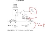
the literature I am reading is given by Pr. Christophe Basso in his book, he derived the transfer function of peak current mode control for boost converter as you can see in the schematic:

boostschematicsPCM.JPG,

the only difference with my circuit is that i have used Ri=1 as I took my currrent sensor is placed in the inductor not the swich. this is the formula he gave in CCM:

boostVerr.JPG


as you cansee the transfer function derived is Vout(s)/Verr(s) and the control here is the voltage error Verr which I tried to implement in PLECS as you see but asfd44 was right ,the placement of the perturbation after the +*- block or before is the same ans I understood why I was getting a DC gain =0. Now, I dont know where should I place the perturbation so I can have the same bode plot given by the equation in baasso#s book?
 

Status
Not open for further replies.

Similar threads

Part and Inventory Search

Welcome to EDABoard.com

Sponsor

Back
Top