Continue to Site

Welcome to EDAboard.com

Welcome to our site! EDAboard.com is an international Electronics Discussion Forum focused on EDA software, circuits, schematics, books, theory, papers, asic, pld, 8051, DSP, Network, RF, Analog Design, PCB, Service Manuals... and a whole lot more! To participate you need to register. Registration is free. Click here to register now.

[SOLVED] Traces on PCB at 2.45 GHz

Status
Not open for further replies.

ndequeiroz

Junior Member level 3
Joined
May 11, 2017
Messages
25
Helped
0
Reputation
0
Reaction score
0
Trophy points
1
Activity points
201
Hi,

I'm studying this harverster circuit


Circuit.png


I have a simple and newbie question, i know that i need to connect all these components with traces, but i know also that can't be arbitrarily, i need to calculate all traces to not affect the circuit behavior, but how can i do that? With quarter wave transformers? Can i use the line calc tool on ADS for this?


Thank you
 

I think my question isn't clear, i used the smith chart tool on ADS to match the antenna with rectifier and i got this:

FinalMatching.png

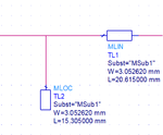
I did the calculation of the microstrip lines in ads line calc tool:

MicroStripMatching.png

I want to insert another trace before my matching circuit, and don't change my matching frequency.


Thanks
 

Design the line impedance for your source impedance (50 Ohm).

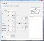
LineCalc.jpg

I put 50 Ohms on Z0 and i get some Width (determines the impedance of the line), but for the length can i determine arbitrary? Or i should set an specific Electrical Length?
 

Status
Not open for further replies.

Part and Inventory Search

Welcome to EDABoard.com

Sponsor

Back
Top