Continue to Site

Welcome to EDAboard.com

Welcome to our site! EDAboard.com is an international Electronics Discussion Forum focused on EDA software, circuits, schematics, books, theory, papers, asic, pld, 8051, DSP, Network, RF, Analog Design, PCB, Service Manuals... and a whole lot more! To participate you need to register. Registration is free. Click here to register now.

[SOLVED] I can't get high frequency output of my Ramp Generator

Status
Not open for further replies.

chandlerbing65nm

Member level 5
Joined
Apr 5, 2018
Messages
80
Helped
0
Reputation
0
Reaction score
1
Trophy points
8
Activity points
709
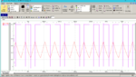
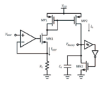
I've been working about this ramp generator circuit (attached file) for my research. Initially I want to have a ramp output of frequency 100MHz to 1GHz but I have a problem because i can only get 20-30kHz ramp signal. In my reference paper, the formula of frequency is f =Vref/(RtCt(Vh-Vl)) or f = Io/CV, but no matter what value I change the parameters(Vref, Ct, Rt and Schmitt trigger sizes) it still would not get a high frequency output, instead I only get a distorted output.

Here are the values of the parameters which I can get a clean ramp output but with small frequency:
Rt = 5k
Vref = 1V
Ct = 1nF
Vh = 0.7V
Vl = 0.25
Vdd = 1.2V

using the formula f =Vref/(RtCt(Vh-Vl)); f = 444.44kHz
but in my simulation output, I only get 32kHz ramp signal.

I use TSMC 65nm technology in my simulation.
I attached my reference paper in this study.


Please someone expert in these things, please I need help. Thank you!
 

Attachments

  • Implementation of a Ramp Generator with Schmitt Trigger Circuit for PWM Modulator Applications.pdf
    577.5 KB · Views: 132
  • ramp generator.PNG
    ramp generator.PNG
    83.2 KB · Views: 405

Hi,

calculate the expected current through Ct for your high frequency.

Klaus
 

I presume you can answer the question yourself when looking on simulation results in detail.

A few hints:
- does MP2 source the expected drain current of 200 µA over the ramp voltage range
- what's the discharge circuit delay from tripping Vp until start of discharge
- what's the discharge current and total discharge time
- discharge circuit recovery time?

100 MHZ to GHz speed is surely a typo
 

threshold voltages of schmitt trigger

Hello all!

I'm doing a simulation about ramp generator(attached image), my problem is that the upper and lower thresholds of schmitt trigger(Vh and Vl) in my simulation are not the same with my calculated values(attached formula image).

Also, instead of ramp wave I get an output of triangular.

Thank you for taking time reading my inquiry. Godbless!
 

Attachments

  • schmittformula.PNG
    schmittformula.PNG
    7.7 KB · Views: 88
  • ramp.PNG
    ramp.PNG
    91 KB · Views: 103
  • schmitt_trigger(schematic).PNG
    schmitt_trigger(schematic).PNG
    17.3 KB · Views: 118
  • ramp generator.PNG
    ramp generator.PNG
    83.2 KB · Views: 107
  • Implementation of a Ramp Generator with Schmitt Trigger Circuit for PWM Modulator Applications.pdf
    577.5 KB · Views: 85

increasing frequency of ramp generator

Hello everyone!

In my simulation of ramp generator, I only get small frequency below 100kHz. How should I increase the frequency to 250kHz? I tried changing Io, Ct and Rt but it only results to bad output.

Here are my values that I get a 33kHz triangular output:
Io = 33uA
Ct = 1nF (0.55V)
Rt = 5k
Vdd = 1.2V

In any of these parameters, Io is the most valuable I think? What value should I increase it to result to better output?

Thank you for your time reading this :-o
 

Attachments

  • ramp.PNG
    ramp.PNG
    91 KB · Views: 94
  • ramp generator.PNG
    ramp generator.PNG
    83.2 KB · Views: 98

The reasons for low ramp frequency are quite obvious. I see two options:
- learn serious electronic design
- don't bother with calculations, simply adjust Ct empirically and try what's feasible
 

Hi,

I don't really know with your circuit. Is the triangle wave due to an inappropriate timing component? What component is functioning as the off timing resistor there?

It may be that one of the MOSFETs has too much capacitance so is slow to turn off, I doubt that 'though, even in my ignorance.

I found that playing with a very similar sawtooth circuit, but discrete components, the off resistor needed to be much larger than the on resistor and if you change that you may have to change the capacitor up or down to get the ramp to peak rather than level off too early or other undesired waveforms.

I doubt this will help, I used a full Wilson. Do you not have the headroom for that or would it not add anything to the design?

sawtooth discrete.PNG
 
I don't really know with your circuit. Is the triangle wave due to an inappropriate timing component? What component is functioning as the off timing resistor there?
You have to guess because the OP doesn't provide any quantitative results. But obviously discharge transistor saturation current makes the down ramp timing. The difference between an imagined ideal circuit and reality.
 
  • Like
Reactions: d123

    d123

    Points: 2
    Helpful Answer Positive Rating
I doubt this will help, I used a full Wilson. Do you not have the headroom for that or would it not add anything to the design?
Big difference in concept there d123. Your schematic uses a fixed frequency 90KHz oscillator to trigger the discharge whereas the original relies on the threshold of the Schmitt trigger. The idea of a voltage controlled constant current source (Iref and Io being basically equal) is it controls the rate of charge to Ct and hence how quickly it reaches the ST threshold. Once reached, the discharge current passes through MN2 to lower it again.

The issues are that to achieve GHz frequencies the stray and intrinsic capacitances must be very small and the switching time of the components very fast. MN2 must also have an extremely low Rds as there is nothing to halt the inflowing current while it tries to discharge Ct.

In summary, the concept is good but to expect it to perform as required is unrealistic.

Brian.
 
How can I reduce the Rds of Mn2 such that I can operate it at max frequency?
 

The best you can do is raise it's gate voltage to maximum but I doubt you would be able to reach more than a few MHz at best. To reach GHz frequencies Ct in parallel with the other capacitances joined to it would have to be below a few pF and I can't see you managing that when the drain-source/gate capacitance of MN2 probably exceeds that already.

Brian.
 
I presume you can answer the question yourself when looking on simulation results in detail.

A few hints:
- does MP2 source the expected drain current of 200 µA over the ramp voltage range
- what's the discharge circuit delay from tripping Vp until start of discharge
- what's the discharge current and total discharge time
- discharge circuit recovery time?

100 MHZ to GHz speed is surely a typo

I don't understand why I need 200uA drain current in MP2. The current that is flowing through the MP2 is 32uA only and the voltage that is charged in the capacitor is 0.5V+.
 

Hi,

Ct = 1nF (0.55V)
If I calculate with a charge time of 95% and a discharge time of 5% and a desired frequency of 100MHz, then

I_charge needs to be: 0.55V x 10nF / (10ns x 95%) = about 580mA = 580,000uA
with the expected 1GHz its 5.8A.

Even with 100MHz I´m by a factor of 2900 OFF the 200uA...

The discharge current is 19 times the charge current. 110A at 1GHz. :)


Klaus
 
I don't understand why I need 200uA drain current in MP2. The current that is flowing through the MP2 is 32uA only and the voltage that is charged in the capacitor is 0.5V+.
You don't need it, but should expect 200 µA by design of the circuit shown in post #1, the nominal Iref value. It looks like either MN1 or MP2 isn't capable of sourcing 200 µA, similarly MN2 can't discharge the capacitor fast enough.

Achieving a few 100 kHz should be no problem with respectively scaled transistors, or smaller Ct capacitance, also multiple MHz should be feasible. 100 MHz or even 1 GHz are out of reach for this circuit topology.
 
I can't get any more bigger than 32kHz clock signal through this circuit. I'm thinking to use a frequency doubler or quadrupler to increase the frequency to 100kHz. XOR gate or another comparator can be used right? what will be better in terms of power and area conumption as well as the distortion of the signal?
 

I don't think you can feed a ramp signal through a doubler or quadrupler and still get a ramp out!


Brian.

No, I mean a clock output that is doubled or quadrupled. That's why I want to use comparators or XOR gate. :grin:

Ramp output be feed into doubler or quadrupler to have clock output.
 
Last edited:

This oscillator resembles a common type using two invert-gates. However the supply can be in the area of 1-2 VDC. Oscillations are excited from a single 1 pF capacitor. The invert-gates are made from discrete transistors. Perhaps it is like a full H-bridge, perhaps it is like a ring oscillator.

Vary the 1k resistor to vary frequency. It's not guaranteed this circuit can go as fast as 500 MHz.

astable H-bridge 1VDC supply 450 MHz.png
 

Ramp output be feed into doubler or quadrupler to have clock output.
I'm confused about what your intention is. Generating a linear ramp is not the normal method of generating clock pulses.

Yes, you could double or 'double double' a square wave signal with an XOR gate but at GHz frequencies it would be very hard to control the delay between inputs and besides, there are other consequences such a jitter to take into account. You also need an extremely fast (might be possible with ECL) XOR gate.


Brian.
 

I'm confused about what your intention is. Generating a linear ramp is not the normal method of generating clock pulses.

Brian.

My professor give me this kind of circuit to generate clock pulses, which is also I just saw his post here in EDAboard about the same matter generating clock pulses with ramp signal.

here is the link of his inquiry here in eda board:
https://www.edaboard.com/showthread.php?t=216084

Now I'm wondering what is his application and purpose in doing clock gen using ramp. He told me that I have to feed the resulting output to a S/H circuit.

What do you think his application or purpose? Its our colloquium this coming Wednesday and I can't ask him about that because it is so embarrassing for me to ask about this 2 days before presentation. He is one of the panel member btw.
 

Status
Not open for further replies.

Part and Inventory Search

Welcome to EDABoard.com

Sponsor

Back
Top