Kick
Full Member level 6
- Joined
- Sep 27, 2010
- Messages
- 344
- Helped
- 16
- Reputation
- 32
- Reaction score
- 15
- Trophy points
- 1,298
- Location
- India,Bangalore
- Activity points
- 3,170
Hi,
I've few doubts related loop antenna simulation in HFSS.
1. While simulating antenna, full PCB layout is required? Most of the example showing just the antenna (without layout). If we simulate antenna alone, what will happen if we add full layout? Will the performance change or same?
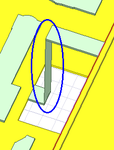
2. Which type excitation is suitable? Now I used Lumper port. Our design is a 2-layer PCB. In bottom ground layer, I made an extension to connect to the port (image). Not sure this is good ides. Please clear.
I've attached the image of antenna model and excitation port.

