Continue to Site

Welcome to EDAboard.com

Welcome to our site! EDAboard.com is an international Electronics Discussion Forum focused on EDA software, circuits, schematics, books, theory, papers, asic, pld, 8051, DSP, Network, RF, Analog Design, PCB, Service Manuals... and a whole lot more! To participate you need to register. Registration is free. Click here to register now.

Push-Pull Convertor load steps

Status
Not open for further replies.

ElecDesigner

Member level 5
Joined
Jul 22, 2014
Messages
94
Helped
4
Reputation
8
Reaction score
5
Trophy points
1,288
Activity points
2,190
Hi.

Working on a push-pull convertor that was designed by somebody else. 50Vin 350Vout, 200W.

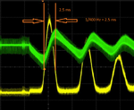
It appears to work fine under steady load but under stepped load conditions the current drawn is unstable. Attached is a scope waveform showing current drawn when a stepped increase in load occurs.

Any ideas on why I'm not seeing just a single stepped increase in current.

Capture.JPG
 

Can be unsuitable feedback loop compensation or too high Q passive filter. Design details needed. Did you monitor Vin and Vout of the converter?
 

Capture2.JPG

The attached shows Vout in green. The variation is small compared with the overall output voltage.
Maybe its hard to know if this is the cause of a problem or the effect.

When you say passive filter, you mean the input filter?
 

Hi,

I´d say it´s caused by the feedback. Especially the relatively long time from peak to peak of about 7ms ...
..and that the (p-p) time is decreasing. --> this is not usual LC behaviour. I rather assume that the controller stops swtiching when yellow line is low. Some kind of discontinous operation.

Klaus
 

In fact the convertor does not stop switching when the yellow line is low, but the Duty Cycle is obviously smaller

- - - Updated - - -

Capture3.JPG

Does anyone know if feedback loop look anywhere near what's expected. I know a lot of factors affect this but any rough idea what be appreciated.
 

Without knowing the full circuit, we can only guess what causes the apparent delay of converter input current. Either it's a property of the feedback controller or modulator, or something happening on the input side like a saturated filter inductor.
 

B.T.W., what's the 50V source? How is it reacting on load variations?
 

The source is a fairly beefy multiphase boost controller being fed from a bench PSU. There is a small variation on Vin coincident with these large current surges but this could easily be voltage drop on the connecting cables. These is a LC filter too but the L is fairly small value and is way over rated in terms of Bsat
 

Does anyone know if feedback loop look anywhere near what's expected. I know a lot of factors affect this but any rough idea what be appreciated.
It is a standard type II network... but it does not say anything.

These is a LC filter too but the L is fairly small value and is way over rated in terms of Bsat
You mean you also have a damped input filter at the input side of the Push-Pull, right ?
 

Yes, the input filter as you suggest.

Regarding the loop compensation - I believe it is common to require type III for these type applications?
 

IMHO it's useless to discuss hypothetical compensation schemes without seeing the full picture. You may have noticed that the characteristic frequency shown in the step response is several orders of magnitudes apart from the time constant implemented in the feedback circuit snippet.
 

Do you have enough slope comp? or too much? the characteristic of your source could well be a factor, put some large electro's and or batteries on the input to decouple this and see if the instability goes away, do you have an input L, as part of a filter? too great an L can cause headaches.

The overall volt loop could be too fast or too close to any LC output filter frequency -

there are a lot of contributors it could be ....
 
I think I've eliminated the input by using different sources, different input capacitances, bypassing the input filter etc.

I'm thinking it might be that the loop is too fast as you mention. Attached is the a snippet of the convertor output stage, I guess there is going to be a fair reaction time given the 1mH?


Capture4.JPG

- - - Updated - - -

Also, I should probably check the resonant frequency of L1 as is might be close to the switching frequency!
 

proper slope comp will reduce the effect of the o/p L , however the outer volt loop still needs thought to avoid oscillation...
 

Your control loop may not have enough gain to deal with the resonant bump from the output filter. If you have a 1000 uF/400V electrolytic available, try to add that with a 2.2 ohm in series over the output to see if this additional damping helps with the problem. I messed around with the gain of a design and could simulate a similar effect on the current waveform.

Without seeing the rest of your circuit, we can only guess at this stage.
 

Attachments

  • damper.png
    damper.png
    20.4 KB · Views: 145
  • peak.png
    peak.png
    272.5 KB · Views: 140
  • gain.png
    gain.png
    16.1 KB · Views: 139
  • load_curr.png
    load_curr.png
    14.4 KB · Views: 134

yes, all is guess work without a proper schematic showing power & control and a few pics showing layout, gain peaking of the LC o/p filter also gives a sharp change in phase. If you have too much slope comp on the current mode then the overall control begins to look like voltage mode - and the LC filter comes into play - a way to help is to add a phase lift circuit (sometimes called a speedup ckt) an RC across the R sensing the Vo, if this is placed near the LC freq it usually helps ...

- - - Updated - - -

across each of R125 - 127 in your case due to the high volts on Vo.
 

Does anyone know a good reference for calculating the required slope compensation for a push-pull convertor?
 

Status
Not open for further replies.

Part and Inventory Search

Welcome to EDABoard.com

Sponsor

Back
Top