Continue to Site
Follow along with the video below to see how to install our site as a web app on your home screen.
Note: This feature may not be available in some browsers.

...and it's doubtful the SG3524 could produce enough voltage to fully drive that many transistors anyway.
Brian.
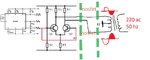
The SG3524 produces a squarewave output that switches high with a small voltage drop then it switches low with a small voltage drop. With low voltage drops then it does not waste a lot of power making heat like your crazy idea of using a sinewave generator and a linear amplifier that gets hot. This SG3524 circuit uses a small amount of PWM to regulate its average output voltage. The output of this SG3524 inverter is a squarewave, not a sinewave.
Modern sinewave inverters use PWM switching for low heating but modulate the high frequency pulses with a low frequency sinewave. Then they smooth the high frequencies away with an output filter.
first im here because before 2 week ago i see one of your...and it's doubtful the SG3524 could produce enough voltage to fully drive that many transistors anyway.
Brian.
thank mr fvm for replyPresumed you want to design an inverter with linear power amplifier rather than usual PWM output stage. Then the output stage must be designed as voltage amplifier similar to a linear audio power amplifier. The output stages you have shown so far are pure switchers and can't achieve linear voltage amplification.
ok mr AudioguruYou did not say how much 220VAC power you want. If you want 500W then a linear audio power amplifier will produce about 400W of heat. If the output from the amplifier is only 4V at 500W then the peak current in the amplifier output is 88A which is a lot of current. The battery that powers this inverter must provide 900W of power.
yes it's alot of power3000W is a lot of power. Why don't you use common ordinary household electricity? A 3000W PWM sinewave inverter will probably produce 225W to 450W of heat.
thanks for explaining mr betwixtBurai - firstly, your English is good, no need to be sorry!
You need to understand there are several ways to generate 220V AC with 3KW capability but it is technically quite difficult. The main problem isn't how you produce the AC, it is simply the amount of current the circuit needs to work properly. Power = Volts x Amps or looking at it the other way, Amps = Power/Volts. So the current needed to produce 3KW from 12V is at least 3000/12 = 250 Amps. That assumes 100% conversion efficiency which is not possible in real life.
You say you want to start from 12V AC (post #8) so the simplest way is a step-up transformer but it would be very large, expensive and heavy (two people to carry it!).
yes but it just a thinking for solution, but it can't be , because it need linear power amplifier and it inefficient also the 250 amp can't be.Where is the 12V AC @250 Amps coming from anyway?
If you want to convert 12 DC to 220V AC there are three practical ways to do it:
1. Build a 'modified' sine inverter. This does produce AC but it is not a sine wave, it is like a square wave with a 0V period before and after the zero crossing time. It is the easiest to build but because the waveform has sudden rising and falling edges, it will not drive some loads properly, in particular, it will not drive motors or transformer loads efficiently and if they do run, they may be noisy or overheat.
2. Build an analog sine inverter. This is a sine wave oscillator and a powerful amplifier to increase the power. I think this is what you originally had in mind. It works, but there is a serious problem, such amplifiers are very inefficient, maybe 70% at best. That means to get 3,000 W out, you need to supply the amplifier with about 4,000W and force remove the 1,000W of heat it will produce. It would also need about 350A of current from 12V to operate it.
3. Build a PWM inverter. This is the most complicated but efficient method, it can reach efficiencies of > 90%. You start by generating a high DC voltage using an efficient high frequency inverter then 'chop' the DC using a PWM driver circuit to produce the low frequency sine wave from it. Because it relies on high speed power switching you can not use transistors like the 2N3055, you have to use power MOSFETs and special gate driver devices. There are many designs on the internet that use this method but I warn you they are complicated to build and, as many on here will tell you, are not forgiving if something goes wrong. I'm sure most people on here who have designed and built PWM power supplies will have seen smoke coming from them!
Brian.