Continue to Site

Welcome to EDAboard.com

Welcome to our site! EDAboard.com is an international Electronics Discussion Forum focused on EDA software, circuits, schematics, books, theory, papers, asic, pld, 8051, DSP, Network, RF, Analog Design, PCB, Service Manuals... and a whole lot more! To participate you need to register. Registration is free. Click here to register now.

DC Electronic Loads with digital control?

Status
Not open for further replies.

asrock70

Full Member level 4
Joined
Oct 9, 2010
Messages
201
Helped
5
Reputation
10
Reaction score
5
Trophy points
1,298
Activity points
3,252
DC Electronic Loads with digiral ciontrol?

It is not a problem to design and build an electronic load as HP 6060B, but it will be complex and complicated analog design.
To solve this 4-channel load would be extremely expensive and complex.

I'm thinking about hardware simple design.
My idea is only two big MOSFET any as IRFP260N.
MISFET is drivers simple amplifier with analog feedback only in Constant current mode.
Current measure on low ohm resistor with current measure amplifier (0-40A (2x20A)).
Voltage measure voltage differential amplifier 0-60V.
Everything else, leave on digital control for example MCU STM 32F373 2x 1MSPS 12dit DAC and 12bit ADC make digital control in Constnt voltage mode, in Constant resistance mode and jump load change.
Clearly, it will not be as fast as an analog feednack, but ....

It's nonsense, or it's worth exploring?
 

Re: DC Electronic Loads with digiral ciontrol?

You have described the essential building blocks of an electronic load.

Yes, it is worth exploring.
 

Re: DC Electronic Loads with digiral ciontrol?

Power MOSFETs made for switching may not be real
happy operated linear. First question is, do you need
I-V linearity or just a particular I at a particular V in
a static DC test?

Next is, do you need more than one quadrant (because
power MOSFETs are not symmetric)?

For my uses (positive DC-DC converter loads) I have
come to prefer a "power RDAC" with a bank of binary
weighted resistors switched by power MOSFETs (not
operated linear, but either "on" or "off"). The resistors
are dead linear and the FETs make no contribution to
the I-V characteristic (sub-% of leg resistance).

Even good test equipment type E-loads have some
ugly attributes like the strange reactance of the load.
Drove me nuts when DC-DC testing because the e-load
would destabilize the converter - both of them trying
to control the output, one the voltage and one the
current.
 

Re: DC Electronic Loads with digiral ciontrol?

Yes, it is worth exploring.

Ok I try it

ill come out of my version big load HP6060.
MOSFET ''module''

Only two MOSFET IRFP260N.
MOSFET is drive Error Amplifer U8B.
On - input 6 is on Resistor R46 and R44 compare negative I_Prog voltage with Positive Current sense voltage.
Current is measure on shunt (R60 || R61) and amplify with differential amplifier U8A.

Current measurement signal is over R66 and R65 counted on summing amplifier U6B I_mon is -10V for full current range more precise -10V for 30A.
Voltage is measurement with differential amplifier U6A and output is -10V for full voltage range more precise -10V for +60V U_Mon


Driver

Signal I_Prog is drive only error amplifier U3A as Constant current mode.
On - input 2 is on resistor R12 or R19 and R15 summing negative voltage I_Mon with CC_Prog voltage 0 - +10V. U3B is for Low Side range R19 is 1/10 R15 is Switched on U4


U2 A and B make from U_Mon and I_Mon 0 -10V voltage 0 - +2.5V for ADC

On D5 was amplifier for driving in CV mode, on D1 amplifier for driving OVC similar OCP. is removed because all this realize digital in MCU

MCU and digital control
for example with STM32F373

CV Mode
in this mode Load maintains on input constant voltage,
OK 12 bit ADC measure U_Mon (1us), compares with desired voltage and increase or decrease CC_Prog.

CR Mode
in this mode Load maintains on input constant resistance,
R=U/I
OK 12 bit ADC measure U_Mon and I_Mon (2us), compares with desired resistance and increase or decrease CC_Prog.

OVP
in this mode Load increase current if voltage on input exceeds the set limit.
Use Comparator in MCU, and compare signal derived from U_Mon.2.5 with Internal Ref or 1/4 1/2 3/4 internal ref and have 4 step of OVP


OCP

in this mode Load decrease current if current on input exceeds the set limit.
Use Comparator in MCU, and compare signal derived from I_Mon.2.5 with Internal Ref or 1/4 1/2 3/4 internal ref and have 4 step of OCP

take it as the first shot.
What do you say?

View attachment Load.pdf
 

Re: DC Electronic Loads with digiral ciontrol?

I would say, break the design down in building blocks and test them individually.
Only after you are satisfied with their operation and are thoroughly debugged, then you start connecting everything together.

I would definitively start with the output stage:
-check for closed loop stability, both in simulation and an actual prototype.
-check for thermal capabilities. You will have to actually mount the Mosfet on its intended heatsink and make temperature rise measurements. From experience, I believe that a single output Mosfet won't be enough, you'll have to parallel devices. But you are the one who has to actually validate this statement.
 

Re: DC Electronic Loads with digiral ciontrol?

So, I'm already tested.
I builded, a great electronics load comparable to the HP6060.
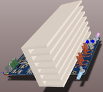
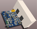
consisted of 4 modules , 2pcs MOSFET on every module , two and two backs to each other.(a wind tunnel arose)
See on picture
1L.png
2L.png
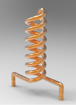
Shunt resistor is from manganin wire winding as low inductance resistor

R1.png

Heating is in real twice higher and I have tester power dissipation 800W on one module for 5 minutes.
Yes in this version is used MOSFET FDA50N50 625W max Power dissipation
 

Re: DC Electronic Loads with digiral ciontrol?

Please show me the calculations:
how does one keep a Tc = 25C while dissipating 625 watt, with real world case-to-heatsink plus heatsink-to- ambient thermal resistances.
 

Re: DC Electronic Loads with digiral ciontrol?

how does one keep a Tc = 25C while dissipating 625 watt, with real world case-to-heatsink plus heatsink-to- ambient thermal resistances.
As far as I understand, the OP claims to have dissipated 800W with two transistors. It requires a heatsink with about 0.5 K/W at 25 °C ambient temperature. That's no impossible with strong blowers, but sounds questionable for the shown heat sink. In any case, a well considered design would use more transistors in parallel to the benefit of a longer lifetime.
 

Re: DC Electronic Loads with digiral ciontrol?

Please show me the calculations:
how does one keep a Tc = 25C while dissipating 625 watt, with real world case-to-heatsink plus heatsink-to- ambient thermal resistances.
625W is in datasheet mentione Absolute Maximum Power dissipation
In our practical experiment we test 800W on module it is 400W on FDA50N50 .
In experiment we the whole module immersed in the cooled flowing oil.
If we look on air and set power on 200 W / MOSFET
T= R x P
Tj-c = Rthj-c x P = 0,20 x 200 = 40K
Tc-h = Rthc-h x P = 0,15 x 200 = 30K (Tecofoil)
Th-a = Rthh-a x P = 0,20 x 200 = 40K
Total 110K

- - - Updated - - -

As far as I understand, the OP claims to have dissipated 800W with two transistors. It requires a heatsink with about 0.5 K/W at 25 °C ambient temperature. That's no impossible with strong blowers, but sounds questionable for the shown heat sink. In any case, a well considered design would use more transistors in parallel to the benefit of a longer lifetime.

If is used wind tunnel (composed of co-located coolers) or use expensive heatsing as Fischer LA 14 Hollow-fin cooling aggregates is possible realize
thermal resistance Rth 0.13 - 0.07 K/W .
But to the point
I am trying to get a cheap load option, so I would like to do it with two transistors. Max power on mobudle let's say 300W tens of minutes and 400W in minuts.

Primarily, it should be cheap, easy to realize, but at the same time as the most profitable possibilities of large profi loads
If I go back to the big variation (the ones on the pictures).If we use full variation one fully fitted and three with fitted only MOSFET and their drivers. is this load full comparable with HP606) but design have around five hundred components.

For new design is upper limit 150 pcs.
Therefore, there is no analogue control CV,CR, OVC,OCC and OPC.
All this should be entrusted to a purely digital controlled via Constant current control.
What I do not know if digital devices will be fast enough.
Let's say that, digital control, has a delay of 5us, 1us ADC, 2us MCU procesing, 3us for DAC set ad analog reaction.
How to judge whether it is enough or extreme lazy?
 

Re: DC Electronic Loads with digiral ciontrol?

If is used wind tunnel (composed of co-located coolers) or use expensive heatsing as Fischer LA 14 Hollow-fin cooling aggregates is possible realize thermal resistance Rth 0.13 - 0.07 K/W.
I know it's possible, but doubting that the heat sink sketched in post #6 is sufficient. Also suggested to operate the transistors at lower junction temperature.

The discussed digital controller topology is well feasible. But the digital control loop speed must be related to the intended tester specification, e.g. current rise time for load steps, output impedance and bandwidth in CC and CV mode which wasn't clearly mentioned yet.

In case of doubt, perform a system simulation of analog + digital control loop.
 

Re: DC Electronic Loads with digiral ciontrol?

Additionally....
the cost of a massive heatsink and blower will be more than that of an additional transistor or two.
Also, for thermal analysis I like to consider room temperature 30C, not 25C. The extra margin may be necessary if the equipment is rack mounted or live in a very warm place (like I do).

Enough of thermal issues. Related to the speed and stability, the digital control loop most certainly has the bandwidth to perform what you want.

Having said this, my personal design philosophy would be that for the inner control loop (that of the power stage plus current sense) to be stable on its own. Some people may disagree with my thinking, but that is what I would recommend.
 

Re: DC Electronic Loads with digiral ciontrol?

Hi,
I'm working on the same concept, two paraller mosfet's operating as a load.
I solved the thermal issue with a good heatsink and a strong fan.
but I face another issue here, I've made 10 channels for testing 10 power supplies, 3 out of the 10 stopped working, the FET's got shortened (drain with source) and I have no idea why that happened.
Original Circuit.JPG
I'm not familiar with FET's but I know they can work with 200V of Vds and 100A..

Who can suggest a better circuit to ensure reliable work of FET's?
 

Re: DC Electronic Loads with digiral ciontrol?

A FET cannot work with 200V*100A. Do the arithmetic.
Those two ratings are corners of the SOA box, and not
the upper right (which is always, always, always clipped).

If the load is unidirectional and feedback controlled and
slow (not toggling) then you might consider some dumb
ol' NPN power transistors (or Darlingtons for ease of drive).
The BJT structure is often more forgiving of abuse (like,
no fragile gate oxide that gets punched out if the source
is not rock solid w.r.t. gate drive, and no ill-controlled
parasitic BJT to light up when the channel gets too hot
- see V*I). Using the channel as the heat dissipator is
a poor idea, power FETs are optimized for switching and
sitting at one of two states and linear high power is not
one of them.
 

Re: DC Electronic Loads with digiral ciontrol?

MOSFET are suited for linear operation, 95 % of recent high power amplifiers are using banks of parallel connected MOSFET with current balancing source resistors.
 

Re: DC Electronic Loads with digiral ciontrol?

I know it's possible, but doubting that the heat sink sketched in post #6 is sufficient. Also suggested to operate the transistors at lower junction temperature.
In case of doubt, perform a system simulation of analog + digital control loop.
Heat sing in post 6 is SK 100 150mm from Fischer, Rth=1.2K/W, if is this heatsing used as one side wind tunnel ceiling AL sheet and apply wind 6m/s have Rth =0.25 K/W.
the concept of the MOSFET module makes it easy to use two or three or four transistors. In fact, just need to recalculate the resistors.
However, the effort is simpler, more affordable solution.
PCB max 100x100mm i.e. max 3 MOSFET

Simulation
For simulation I use MULTISIM and I do not know how to simulate digital control

- - - Updated - - -

I'm not familiar with FET's but I know they can work with 200V of Vds and 100A..
When we are dealing with large currents and loads.
You need to be aware, 1mili Ohm , for example in connector or in wire, PCB is in power dissipation 10W for 100A
On picture you have 35m Ohm shunt for 100A it is 350W power disipation only on shunt
Similar to that with transistor legs (pin) and soldering to PCB.
The load for such large currents can be dealt with as a "blacksmith's work" or you have to go through the massive parallelization, for example 8MODTET and 8 current shunt then it will be 12,5 A on MOSFET.
 

Re: DC Electronic Loads with digiral ciontrol?

Heat sing in post 6 is SK 100 150mm from Fischer, Rth=1.2K/W, if is this heatsing used as one side wind tunnel ceiling AL sheet and apply wind 6m/s have Rth =0.25 K/W.
Did you measure the Rth value? What's the fan sound level?

Let's assume the heat sink parameters are real, it doesn't weaken the reasoning for a different transistor area to heat sink size trade-off. But I believe, everything has been said so far.

For simulation I use MULTISIM and I do not know how to simulate digital control.
Make behavioral models for digital controller elements, e.g. time discrete sampling, dead time, PI controller.
 

Re: DC Electronic Loads with digiral ciontrol?

When we are dealing with large currents and loads.
You need to be aware, 1mili Ohm , for example in connector or in wire, PCB is in power dissipation 10W for 100A
On picture you have 35m Ohm shunt for 100A it is 350W power disipation only on shunt
Similar to that with transistor legs (pin) and soldering to PCB.
The load for such large currents can be dealt with as a "blacksmith's work" or you have to go through the massive parallelization, for example 8MODTET and 8 current shunt then it will be 12,5 A on MOSFET.

my shunt is 0.35 mOhm and I'm driving 38A in my circuit (100 is the maximum the FET can use). so the power on shunt is (38^2)*0.35/1000~0.5W where all the power dissipation is on the FET.
I'm using two parallet FET so each FET can drive 16A (if they are simmitric).
 

Re: DC Electronic Loads with digiral ciontrol?

Few notes about choosing a MOSFET transistor for Electronics Load
I compare IRFP 260N and FDA50N50
ParametersIRFP260NFDA50N50
Vdss200V500V
Rds40mOhm90mOhm
Avalanche Current50A48A
Operating.temp175C150C
Max power disipation300W625W
Thermal Resistance J-C0,5 C/W0,2 C/W
Csii4100pF5000pF
Price in China 5pcs3$5$
The IRFP260n is cheaper and tolerates a higher temperature of 175C, but the FDA50N50 seems to have a much better heat transfer pad between the chip and the body of the transistor, therefore it has 2x all loss power and lower RJ-C.
Teoretical power lost on transistor with current limit 15A and use max power disipation, does not take into account what can be done on the cooler.

SOA1.png

I'm probably using FDA50N50 and place 3 pcs on one modul , if limiting current on 15A over transistor we have teoretical Load max voltage 100V max current on module 45A max pulse power lost 1.8kW :wink: max long time power lost limited by used heat sing and fan.
FDA50N50 is 500V transistor it gives hope for high voltage endurance and enables easy load carrying with resistance up to 400V, if desired .
If it's time to give the module a schematic tonight
 

Status
Not open for further replies.

Similar threads

Part and Inventory Search

Welcome to EDABoard.com

Sponsor

Back
Top