mrinalmani
Advanced Member level 1
- Joined
- Oct 7, 2011
- Messages
- 463
- Helped
- 60
- Reputation
- 121
- Reaction score
- 58
- Trophy points
- 1,318
- Location
- Delhi, India
- Activity points
- 5,285
Hi!
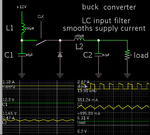
Is an input LC filter required in a buck topology solar MPPT?
Without an input filter, the very nature of a buck converter would result in discontinuous current being drawn form the solar panels. How can one expect high efficiency if the panel current is discontinuous?
Surprisingly, if we just google search for "MPPT circuit" and see the images, they all lack an LC input filter.
Another person just designed a buck based MPPT and without an input filter and was managing an efficiency of 70% power from the panel. I wonder how it even reached 70%. If it is a buck based converter with 50% duty cycle, the panel efficiency should not be more than 50%, since half the duty cycle it would simply be OFF. (Probably the self inductance of the cable connecting MPPT to the panels did some good work)
My question is:
Is an input LC filter required for a buck based MPPT?
Thanks
