Continue to Site

Welcome to EDAboard.com

Welcome to our site! EDAboard.com is an international Electronics Discussion Forum focused on EDA software, circuits, schematics, books, theory, papers, asic, pld, 8051, DSP, Network, RF, Analog Design, PCB, Service Manuals... and a whole lot more! To participate you need to register. Registration is free. Click here to register now.

IR2110 Full-Bridge, heating-coil-heat-distribution experiment, what about dead-time?

Status
Not open for further replies.

David_

Advanced Member level 2
Joined
Dec 6, 2013
Messages
573
Helped
8
Reputation
16
Reaction score
8
Trophy points
1,308
Location
Sweden
Activity points
12,219
IR2110 Full-Bridge, heating coil heat distrubution experiment, what about dead-time?

Hello.

I have heard that if a heating coil(it isn't a coil as in inductance coil, it's simply a resistive heating element wound as a coil) is supplied with current in only one direction the heating of the coil is uneven on some ways, but that if the current is alternating in direction the heat distribution across the coil will even out.

I have no idea if that's true but it is relevant to a vaporizer project I have been talking about here though quite a while ago.

So I am setting up a experiment to test that.

My thought is to use a 12V @ 16A power supply(a former XBOX console power supply) to supply the current to a large 1Ω coil made out of 0,8mm thick SS316 wire by means of a H-bridge made with 2*IR2110 driving 4*IPP039N04L N-channel MOSFETs. With such a circuit I should be able to first supply the coil current by turning on/off only one current path through the H-bridge, and observe how the coil starts to glow as the heat gets very high, as if I where supplying the coil with a PWM signal. Then do the same thing again but this time every other PWM on-time will be supplied by one of the H-bridge current paths and the other on-time supply the current in the reverse direction with the other H-bridge current path.

Here is the circuit(I am about to go into my work room to dead-bug build the circuit):
IR2110 vape coil experiment.png

I am thinking about how to generate the signals for the 4 MOSFETs, the first case in simply a PWM signal feeding into HIN1 and LIN2(or HIN2 and LIN1). But the second case is more difficult to think about how to generate in my mind.
I have a couple Arduino Due, a Digilent Analog Discovery and a Rigol arbitrary function generator, so I have plenty of options, but how to make those second case PWM singals most easily?

And what about dead-time? I have read that the diode and resistor that I have put in series with the MOSFETs gates is suppose to introduce some dead-time, but I can find no info on the validity of that statement, but many people have written online that the IR2110 includes dead-time in the circuit internally but the datasheet is not full of information, it does have some timing value that I don't understand what it is, it's named "Delay Matching, HS & LS Turn-On/Off" and is specified as 10nS.

I don't know how to determine the requirements for dead-time in this case, do I have to worry about that?
I have the MOSFETs on a monster heat-sink and the time that the MOSFETs will be switching shouldn't be more than 5-30 seconds(supplying the 1Ω resistance coil with 12V@12A should heat it up pretty quickly at a PWM frequency of 100kHz, but I might also use something more along 1kHz, in any case the heat up is going to happen quickly).

I will go and build it now but I would rather see what you think than simply trying it out...

Regards
 

Re: IR2110 Full-Bridge, heating coil heat distrubution experiment, what about dead-ti

but how to make those second case PWM singals most easily?
What are the second case PWM signals ? If you are referring to the complementary switches of the Full Bridge, a simple inverter might do the job.

but many people have written online that the IR2110 includes dead-time in the circuit internally but the datasheet is not full of information, it does have some timing value that I don't understand what it is, it's named "Delay Matching, HS & LS Turn-On/Off" and is specified as 10nS.
Delay Matching is the dead-time those people were talking about. Figure 6 explains it pretty well, I think.

I don't know how to determine the requirements for dead-time in this case, do I have to worry about that?
Depends on the switching times of the MOSFETs and the internal dead-time of the driver. If MOSFETs switch ON/OFF faster than the dead-time, you do not have to worry.

- - - Updated - - -

I have read that the diode and resistor that I have put in series with the MOSFETs gates is suppose to introduce some dead-time, but I can find no info on the validity of that statement
Yes it is true. The gate resistor will slow down the turn ON while the diode will fasten the turn OFF, in general...

- - - Updated - - -

I have heard that if a heating coil(it isn't a coil as in inductance coil, it's simply a resistive heating element wound as a coil)
PWM frequency of 100kHz, but I might also use something more along 1kHz
At those frequencies, the inductance will most likely show its influence i.e. will NOT be a resistive element as you seems to want. It seems that you want a heater, but the coil+those frequencies suggest you are trying to do an induction heater.
 

Re: IR2110 Full-Bridge, heating coil heat distrubution experiment, what about dead-ti

Hi,

Equal heating:
With DC current there will be very even power dissipation along the heating element, but you may expect some
Deviation at the solder joints at the beginning and end of the wire. This is caused by thermocouple effects or peltier effects by joining different materials.
I doubt the difference is easy to measure, because it will be very small. And a lot of other parameters influence the temperature.

Your circuit....I see some issues:
* a wound heating element will create some inductance. If you want to avoid (reduce thus) then use bifilar winding.
* i recommend to calculate with some stray inductance in the heating element. (Mathematics and high voltage peak protection)
* the 1k gate-source resistor (shown in many internet schematics, but never in IR2110 datasheets) reduce the benefit of high ohmic gate of a Mosfet.
* thus you need high value bootstrap capacitors to ensure high ON time for the highside FETs.
* you show connectors instead of Mosfets. But you need short, low inductance connections between Mosfet and IR2110. Even with a good PCB layout I recommend wiring shorter than a couple of cm.
* you talk about dead time. Don't search the internet for doubtful informations. Look at Mosfets_manufacturers or driver_manufacturers application notes. They have very good, detailed informations. About every manufacturer.

There are Mosfet drivers with adjustable dead time.

You say "monster heatsink" ...if you need big ones, then there's something wrong with your design. A good design for this application may work without heatsink.

For a good design you need to calculate with PWM frequency and range of duty_cycle. I see no need for 100kHz switching frequency.
I even don't see the need for 1kHz here....or is your temperature measurement fast enough to detect temperature change wihin a part of a millisecond?

Dead time is urgent to avoid cross conducting of high side and low side FET....this is independent of switching frequency.
But switching loss increases with increasing switching frequency...therefore I'd reduce switching frequency to a minimum.

I don't know your PWM scheme, but I recommend to keep the low side FET continously ON and PWM the high side of the opposite half bridge.

Klaus
 

Re: IR2110 Full-Bridge, heating coil heat distrubution experiment, what about dead-ti

I have heard that if a heating coil(it isn't a coil as in inductance coil, it's simply a resistive heating element wound as a coil) is supplied with current in only one direction the heating of the coil is uneven on some ways, but that if the current is alternating in direction the heat distribution across the coil will even out.

Wrong; the same current flows through the conductor at every point and the heat production (per unit length of the wire) is constant (provided the wire is uniform). It does not matter which way the current flows.

But what is the hypothesis you are trying to prove? What are the theoretical support for the hypothesis?
 

Re: IR2110 Full-Bridge, heating coil heat distrubution experiment, what about dead-ti

In a short, there seem to be no advantage of the H-bridge against a single transistor when driving a resistive heater. If pwm should be utilized to control the heating power (is it so?), the frequency can be in a low kHz range, mainly commanded by the acceptable power supply ripple current and respective bypass capacitor sizing, otherwise it's just on-off control.

To care for residual heater and wiring inductance, the load should be equipped with a free wheeling diode.

There would be a different situation if you utilize a transformer to match heater voltage, but this is apparently not intended.
 

Re: IR2110 Full-Bridge, heating coil heat distrubution experiment, what about dead-ti

Gate drive networks should not be the dead time control,
they are for controlling dV/dt (FET ratings there, and some
impact on EMI output / overshoot). At least, when you
have the independent control of both.

Dead time is for cross conduction once the gate drive
networks are set. Falling dead time, you look at the SW
node undershoot (you would like to not turn on the
body parasitic diode D-B, but also may be looking to
"soft switching" as an efficiency bonus so neither early
(hard switch) or late (forward diode losses) are wanted.

Rising dead time you probably just want break before
make, no leading edge shoot-through spike in the totem
pole (look at magnitude of current sense leading edge
as you tune).

Backing into it from benign-nonideal, toward "might blow
up" conserves victims... plan your tweaking if you are
on a budget, dollars or delivery time.
 

Re: IR2110 Full-Bridge, heating coil heat distrubution experiment, what about dead-ti

Thanks for all the answers, they have sure given me some food for thoughts.

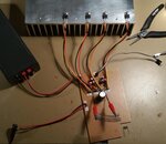
Just ta clarify, I have never used a H-bridge before and due to what I have been told about the heating of a coil I thought that I should make a test circuit to try it out(if nothing else just to use a H-bridge, hmm... I know realize that I probably should have put this thread in the beginner section of the forum. Sorry about that). What Klaus wrote makes me think that my slopy circuit construction is really bad. But I have gone over the circuit 20 times and have powered it on without any smoke so that is at least a good start, this circuit isn't meant to be more than an experiment so I will go ahead and see what will happen. Here's a picture of my circuit, not exactly short wires....:
circuit.jpg
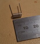
coil.jpg

I measured a coil actually used for this purpose at 100kHz and my cheap Mastech LCR-meter read 0,246µH which was more than I would have thought, although that was when measuring in series model mode, in parallel model mode the reading was over 1µH.
The coil I measured is seen in the picture in the lower right corner, the coil connected to the circuit is hugely oversized as you can see by the comparison.

In the vaporizer I mentioned I am using a buck-converter, it could use PWM but I have chosen to go with using filtering components mostly because it makes the digital control loop easier, at least from my perspective as the current measurement becomes easier and the math becomes easier.

- - - Updated - - -

The monster heat-sink is by no means thought of as a good design, it is simply a way to experiment with high-current switching circuits without any real insight into the amount of heat dissipation that will occur. I just pulled out my largest heat-sink and went on with building the circuit, I get an headache from thinking about how to calculate the power losses in the MOSFETs although I have read about how it is done several times.

But about that second signal, I thought that first I will pulse current through one H-bridge leg(on-duration) and then have an off-duration just as if it was a PWM signal, then I thought I would do the same but this time every other on-pulse would be drawn by the other H-bridge leg, so the current would go, from the coils perspective:

0A -> +12A -> 0A -> -12A -> 0A -> +12A -> 0A -> etc.

Isn't that at least true?
 

Re: IR2110 Full-Bridge, heating coil heat distrubution experiment, what about dead-ti

If I'm understanding correctly your trying to see if and alternating current will heat your coil quicker and more evenly. I don't think so but I have made and observation that you might find interesting. When I first saw this thread I thought of two resistive elements that I might observe to see if there was anything too this. Since I don't have and electric stove I went to my pop up toaster. I didn't tear it apart to find out but it looks like a wire laid out in a zig zag pattern over a metal backing plate. What I noticed is that the wire would start glowing red near the bottom first and then progressively upward until the whole wire was glowing red hot. I always thought it operated on AC voltage but now it makes we wonder if it operates on DC and that is the reason the wire doesn't heat up uniformly. But I'm thinking there is probably another explanation for why it does this.
 

Re: IR2110 Full-Bridge, heating coil heat distrubution experiment, what about dead-ti

Current passing through a conductor will produce heat that depends on the current and the resistance at that place. Unfortunately you cannot measure heat and the only thing that can be meaningfully measured is the temperature. But the heat produced locally diffuses to nearby area and this loss of heat from the surface and the two ends makes accurate measurements difficult. The loss of heat from the surface and the two ends and the internal diffusion of heat from one part to another depends on the local temperature. Thus the temperature becomes a function of time and position (space) and the temperature profile becomes very difficult to calculate except for simple cases like a infinite uniform rod in a temperature bath (temp of the environment does not change).
 

    V

    Points: 2
    Helpful Answer Positive Rating
Re: IR2110 Full-Bridge, heating coil heat distrubution experiment, what about dead-ti

The heater coil has slightly higher resistance at high frequent AC due to skin effect, but it's almost negligible for the given (frequency, wire diameter, resistivity) parameters. That's why I suggested a simple one transistor switcher.

Non-uniform heat capacity and heat sinking into the mounting affects temperature distribution. That's just normal and hasn't to do with AC or DC supply.
 

    V

    Points: 2
    Helpful Answer Positive Rating
Status
Not open for further replies.

Similar threads

Part and Inventory Search

Welcome to EDABoard.com

Sponsor

Back
Top