rohithadpad
Newbie level 6
- Joined
- Dec 15, 2017
- Messages
- 12
- Helped
- 0
- Reputation
- 0
- Reaction score
- 0
- Trophy points
- 1
- Location
- Pune, Maharashtra, India
- Activity points
- 118
Hello,
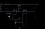
I have used PI expert to design a dual output voltage power supply 5V and 12V. 5V is the one being regulated and it needs to be fairly stable as it supplies sensitive circuits. The 12 V supply is only feeding a relay, so it is allowed to vary. The output is 5.6V, where I need to get 5V. For flyback loop, I have used TL431 and optocoupler PC817.
I have also used zener diode 5.5V instead of the TL431. But when I used zener the output voltage is 6.12V
I am struggling to understand what is wrong..?.
Any suggestions would be most welcomed.