Continue to Site

Welcome to EDAboard.com

Welcome to our site! EDAboard.com is an international Electronics Discussion Forum focused on EDA software, circuits, schematics, books, theory, papers, asic, pld, 8051, DSP, Network, RF, Analog Design, PCB, Service Manuals... and a whole lot more! To participate you need to register. Registration is free. Click here to register now.

[SOLVED] LTSpice-coupled model

Status
Not open for further replies.

CataM

Advanced Member level 4
Joined
Dec 23, 2015
Messages
1,275
Helped
314
Reputation
628
Reaction score
312
Trophy points
83
Location
Madrid, Spain
Activity points
8,409
Hello everyone,

I wanted to check the coupled model in LTSpice. The reason is to check the validity of the model and then derive using the terminal equations (port equations) relations between transformer parameters (leakage, magnetizing) and parameters of the coupling model (L1,2 and k).
(I did this because the equation LTspice suggests did not convince in other threads e.g. this)

However, I have found that the model of coupled inductors does not match very well.
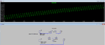
In the picture below, I have represented the difference between the current through V1 and through V2, and as can be seen, it is fairly large.
Likewise, I have measured the difference between voltage sources in order to get a feeling about what is the order of magnitude of the difference between same quantities and it was in the hundreds of micro-[unity].
For example, V1-V2~ around 170 uV and I(R1)-I(R2)~ around 170 uA.

Taking into account the maximum step for the simulation (1 us) and the transient is in steady state, I see resonable values for I(R1)-I(R2) and V1-V2, but not reasonable for I(V1)-I(V2) because it is in the range of mA.

Is this behavior expected ? Can anyone else check this ?
P.D.:I am using LTSpice XVII.

Thank you for your time !
 

Attachments

  • coupledModel.png
    coupledModel.png
    28.6 KB · Views: 107

You forgot the default 1m series resistance of inductors, must be set to 0 to make the equivalent circuit equal.
 
  • Like
Reactions: CataM

    CataM

    Points: 2
    Helpful Answer Positive Rating
Perfect match ! Thanks.

I want to leave here the transformer model using coupled inductors in order to leave a clear model for the ones who want to model their transformes using coupled inductors.
Personally, I would go with the ideal transformer model with magnetizing inductance (coupled inductors with k=1). The rest of the parasitic elements are modeled separately, with additional elements.

Transformer modelling using coupled inductors:
The coupled inductors are defined as follows: L1,L2 and k.
The transformer we will model includes: Ll1 (primary leakage inductance), Lµ (magnetizing inductance referred to the primary), Ll2 (secondary leakage inductance), N1 and N2 turns.

The equations used are as follows:

  • Turns ratio equation: L1/L2=(N1/N2)2
  • L1=Ll1+Lµ (primary open circuit inductance) => Ll1=L1·(1-k)
  • L2=Ll2+Lµ·(N2/N1)2 (secondary open circuit inductance) => Ll2=L2·(1-k)
  • Lµ=L1·k=L2·k·(N1/N2)2

Below is the model check, and matches perfectly with the coupled model.
L3 is the primary leakage inductance, L4 is the magnetizing inductance referred to the primary and L5 is the secondary leakage inductance referred to the primary.
One point is that in order to check the transformer model, one needs to transfer all parameters to the primary (or secondary), so the load resistance must be transferred as well.
One check is I(R1)-I(R2)*0.5 (because the turns ratio N1/N2 in that example is 0.5). If I(R1)-I(R2)*0.5 is ~0, then checking is complete and the model is accurate.
 

Attachments

  • Xformer.png
    Xformer.png
    19.4 KB · Views: 96
Last edited:

You have changed to the standard transformer equivalent circuit with ideal transformer, respectively transformed impedances. See also https://www.edaboard.com/threads/347461/

The equivalent circuit in post #1 seems to model the coupled inductors also correctly, after correcting the default series resistance. It's of course restricted to a certain range of k and n values.
 

You have changed to the standard transformer equivalent circuit with ideal transformer, respectively transformed impedances. See also https://www.edaboard.com/threads/347461/
I already read that thread before opening this thread. In post #1, if you click on "this", you will see it is the same.
The reason for this thread is because in that thread, LTSpice was claiming leakage=L*(1-k^2) (post #1 and post #11 in that thread). I have shown in this thread that using the usual relations (e.g. L1/L2=(N1/N2)^2), the leakage has different equation. Of course, I might misunderstand what LTspice refers to with "L" (we believe it is the main inductance but is not, as shown in post#3 in this thread, which furthermore , "k" is not even squared).

The equivalent circuit in post #1 seems to model the coupled inductors also correctly
The point of this thread was to check the "T" equivalent circuit of 2 coupled inductors, and once I have checked that it works (with your help), I have shown the relationship between xformer parameters and 2 coupled inductors.

If one wants to model their real xformer with 2 coupled inductors ("k" different than 1), post #3 equations (this thread) should be used. However, like I have said, I would go with the ideal xformer + magnetizing (coupled inductors with k=1) and model the rest with additional components.
 
Last edited:

Status
Not open for further replies.

Part and Inventory Search

Welcome to EDABoard.com

Sponsor

Back
Top