Continue to Site

Welcome to EDAboard.com

Welcome to our site! EDAboard.com is an international Electronics Discussion Forum focused on EDA software, circuits, schematics, books, theory, papers, asic, pld, 8051, DSP, Network, RF, Analog Design, PCB, Service Manuals... and a whole lot more! To participate you need to register. Registration is free. Click here to register now.

OPA541 as voltage follower (Buffer)

Status
Not open for further replies.

ctzof

Full Member level 3
Joined
Mar 1, 2012
Messages
157
Helped
12
Reputation
24
Reaction score
11
Trophy points
1,298
Location
Munich
Activity points
2,516
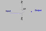
I want to use OPA541 as a buffer simply to provide more current on the output. On simulation level everything works fine, any way the circuit is simple enough. Recently I bought an OPA541 and try to build everything but the circuit simply doesn't work as expected. Attached you can find the circuit topology. As input I used a square wave at 1kHz with vpp 4 V (0-4V) and connect the output directly to the osci. My output is a distorted signal which seems to oscillate up to V+ but it doesn't follow the input. I should say that no decoupling or other type of capacitor was used in this phase. Does anybody have an idea what is wrong?
opa541.png
 

Hi,

I should say that no decoupling or other type of capacitor was used in this phase.
--> Read section 9 and section 10 of the datasheet. It is very clear in this.

As input I used a square wave at 1kHz with vpp 4 V (0-4V)
With high dV/dt you may overdrive the input stage of this relatively slow OPAMP causing instabilities.
The OPAMP´s output is limited to about 6V/us slew rate...
--> I recommend to limit the input slew rate to an appropriate value.

and connect the output directly to the osci.
Often this is no good idea, because a scope cable my be highly capacitive. And capacitive loads are difficult to drive ... causing ringing or oscillations.
--> a small series resistor should prevent from oscillations.

My output is a distorted signal which seems to oscillate up to V+ but it doesn't follow the input.
--> A scope picture with input and output signals could give additional information.

Added:
Also check "Input common mode voltage range" and "Output voltage swing".
--> I recommend to use higher supply voltage.

Klaus
 

Problem solved. probably wrong or bad connection. The opamp can pass sine wave with up to 400khz without any distortion or amplitude mismatch. Thanks anyway for your feedback
 

Status
Not open for further replies.

Similar threads

Part and Inventory Search

Welcome to EDABoard.com

Sponsor

Back
Top