Continue to Site
Follow along with the video below to see how to install our site as a web app on your home screen.
Note: This feature may not be available in some browsers.
Hello Enzy,
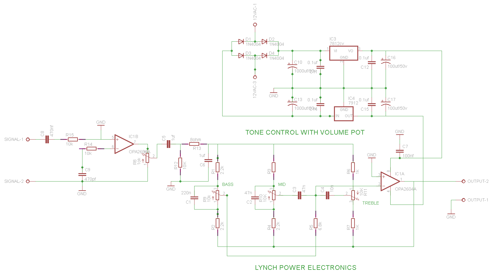
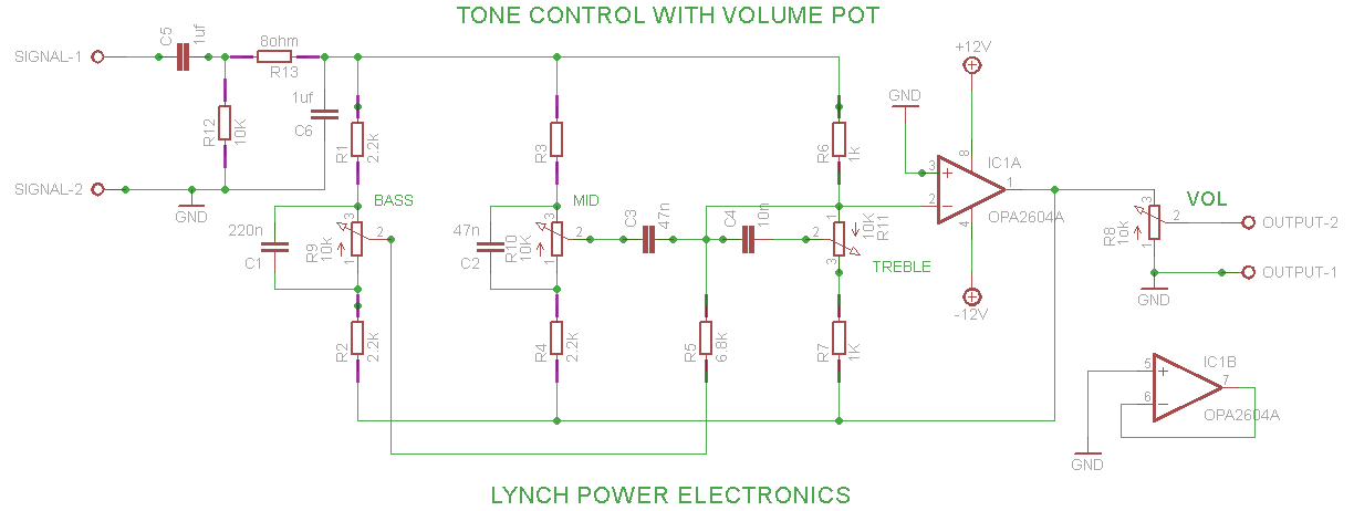
I hope Output 1 isn't a real output, but your ground for Output 2.
Regards,
Relayer
Hi,
The circuit is a classical circuit.
I recommend:
* use high quality foil capacitors
* use high quality pots
* ceramic capacitors for the supplies
Some further improvements, if you like:
* maybe use a better Opamp
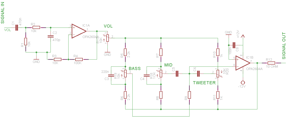
* use a low frequency highpass filter at the input to avoid DC
* and a high frequency lowpass filter at the input to avoit Opamp input overdrive
* a low value capacitor as direct feedback at the Opamp
Klaus
* and a high frequency lowpass filter at the input to avoit Opamp input overdrive...
Hi,
still missing the capacitors at the supply.
Klaus
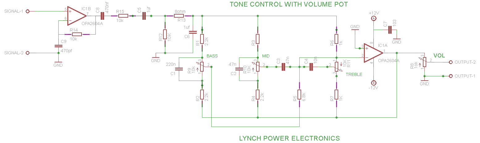
Then comes the sound control stage.470nF --> 10k (to GND) --> 10k (series) --> 470pF (to GND) --> OPAMP buffer
Hi,
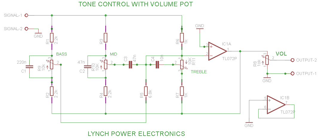
EAGLE: There is a mess with the junction dots. I wonder why, because I usually don't need to set/delete junction dots on my own.
It's automatically done by EAGLE....just use an appropriate grid setup.
If you use a dual supply, then you need at least two capacitors.
Input filter and buffer:
I almost wrote it like the schematic should look like. From left to right:
Signal input, then:
Then comes the sound control stage.
Opamp Buffer = voltage follower
Klaus