Continue to Site

Welcome to EDAboard.com

Welcome to our site! EDAboard.com is an international Electronics Discussion Forum focused on EDA software, circuits, schematics, books, theory, papers, asic, pld, 8051, DSP, Network, RF, Analog Design, PCB, Service Manuals... and a whole lot more! To participate you need to register. Registration is free. Click here to register now.

Interleaving of multi-phase buck converters for low Vout high current applications

Status
Not open for further replies.

bhl777

Full Member level 6
Joined
Sep 30, 2008
Messages
363
Helped
0
Reputation
0
Reaction score
0
Trophy points
1,296
Activity points
5,140
Hi All, I was looking at some datasheet of the interleaved buck converters.

Usually people design interleaved buck converter, and I am curious what is the problem if we do not have good interleave?

One drawback I can see is the output voltage ripple cancellation effect. Having a good phase shift can maximumly reduce the output voltage ripple. In addition to that, is there any other reasons we should use the interleave?

Thank you!
 

Output ripple voltage, which you have mentioned, is one reason.

Input ripple current, is another.

Let's view a quick example:
Imagine a 1.5vout @ 100 amp converter, fed from a 12 volt supply. Switching at a modest 100 Khz, (10 us).
Assuming ideal components, the duty cycle would be 12.5%. Or 1.25 us pulses.
The poor 12 v supply would have to somehow provide 100 amps for 1.25 us, followed by 8.75 us of nothing.

If now you have a six phase interleaved converter, each of the pulses would be reduced by 1/6, or 16.6 amps, and spread over 7.5 us of the switching period.

Far easier to decouple, don't you think?
 
  • Like
Reactions: bhl777

    bhl777

    Points: 2
    Helpful Answer Positive Rating
Output ripple voltage, which you have mentioned, is one reason.

Input ripple current, is another.

Let's view a quick example:
Imagine a 1.5vout @ 100 amp converter, fed from a 12 volt supply. Switching at a modest 100 Khz, (10 us).
Assuming ideal components, the duty cycle would be 12.5%. Or 1.25 us pulses.
The poor 12 v supply would have to somehow provide 100 amps for 1.25 us, followed by 8.75 us of nothing.

If now you have a six phase interleaved converter, each of the pulses would be reduced by 1/6, or 16.6 amps, and spread over 7.5 us of the switching period.

Far easier to decouple, don't you think?

Hi schmitt trigger, thank you for your help! In case we have an LC input filter, do you think the input current will still be a problem of poor interalveve? Thank you!
 

In case we have an LC input filter, do you think the input current will still be a problem of poor interleave?
Instead of asking for guesses, why not calculate input current and voltage ripple and determine filter capacitor current rating in you application?
 

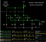
Simple simulation of triple interleaved buck converter. The 3 clocks control 3 'analog switches' which are oversimplified components.

Notice the waveform of current drawn from the supply. It is not so jagged, thanks to the effect of interleaving. It has no LC input filter.

Also notice the small amplitude of AC current ripple at the output capacitor.

triple interleaved buck converters clk-driven 10V 20A.png
 

Simple simulation of triple interleaved buck converter. The 3 clocks control 3 'analog switches' which are oversimplified components.

Notice the waveform of current drawn from the supply. It is not so jagged, thanks to the effect of interleaving. It has no LC input filter.

Also notice the small amplitude of AC current ripple at the output capacitor.

View attachment 141455

Hi BradtheRad, thank you! Can I say "it is case by case to say that input ripple current is impacted by poor interleave"? Do you have an idea what could also go wrong in addition to I_in and output ripple with a bad interleave?

Thank you!
 

Hi BradtheRad, thank you! Can I say "it is case by case to say that input ripple current is impacted by poor interleave"? Do you have an idea what could also go wrong in addition to I_in and output ripple with a bad interleave?

Thank you!

In regard to interleaving, you can find threads which bring up the question about dissimilar inductor values, and imbalances in Ampere levels through them. Switching devices might have variations in 'On' resistance.

If it creates problems then a designer might wish to 'fine-adjust' duty cycles, on/off timing, etc. Perhaps there is an automatic method to achieve this.

It will require a lot of experimentation with hardware, to do sufficient testing to discover what problems might crop up.
 

For 2 phase Buck, the normalized ripple current is reduced to 25% max at duty cycles of 1/4 and 3/4 and is null at 0, 1/2 and full duty cycle.

For a 3 phase Buck the max ripple current is 16.7% with nulls at 0, 1/3, 2/3 and full duty cycle.

For a 4 phase Buck the max ripple current is 12.5% with 5 null duty cycle points for ripple.

and so forth.
 
Last edited:

Status
Not open for further replies.

Similar threads

Part and Inventory Search

Welcome to EDABoard.com

Sponsor

Back
Top