Continue to Site

Welcome to EDAboard.com

Welcome to our site! EDAboard.com is an international Electronics Discussion Forum focused on EDA software, circuits, schematics, books, theory, papers, asic, pld, 8051, DSP, Network, RF, Analog Design, PCB, Service Manuals... and a whole lot more! To participate you need to register. Registration is free. Click here to register now.

Simple transistor logarithmic RF preamplifier for 0-30MHz

Status
Not open for further replies.

neazoi

Advanced Member level 6
Joined
Jan 5, 2008
Messages
4,119
Helped
13
Reputation
26
Reaction score
15
Trophy points
1,318
Location
Greece
Activity points
36,918
Simple transistor logarithmic RF preamplifier for 0-30MHz, to replace the RF (and AF, as it is reflexed) preamplifier in this schematic **broken link removed**
This way I can avoid thr RF preamp from directly rectifying strong out of band stations, without them passing from the regenerative detector.

Can it be done?
Good log performance is not of interest, just a modest performance should be enough.

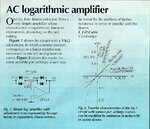
I have seen the attached circuit with great interest, but this is for audio. I wonder if it can be transformed to discrete components for audio AND RF at the same time.
PS. I am not good in simulators, perhaps one could help more.
 

Attachments

  • ac_logarithmic_amplifier.jpg
    ac_logarithmic_amplifier.jpg
    113.7 KB · Views: 101

Logarithmic amplifiers are by nature nonlinear circuits and cause strong intermodulation if you supply it with more than one RF input signal. I don't see how they could serve the intended purpose.

A typical usage of logarithmic amplifiers is a high dynamic level detector in spectrum analyzers or radar systems. They are not suited to decode AM signals.
 
  • Like
Reactions: neazoi

    neazoi

    Points: 2
    Helpful Answer Positive Rating
I agree with FvM, you would be doing almost the opposite of what you wanted.

Don't confuse logarithmic amplifiers with AGC. Log amps work on the wave shape, cycle by cycle whereas AGC works on the average envelope of the signal, in other words on its average strength. AGC is what you want but it is very difficult to derive a suitable voltage with regenerative detectors which by their very nature become oscillators in their own right to receive SSB and CW.

Brian.

Thanks both, you saved me a lot of time. I was thinking that the log amp could handle both strong and weak stations at the SAME time and amplify them at the SAME time unequally. Which is exactly what needed.

The AGC however is not what I need, because the AGC will force the RF preamp to have less gain by the exixtence of a strong out-of-band signal, so this will affect the gain in the wanted in-band signal as well.

I was looking also these audio compressors **broken link removed** but I think these are a form of AGC aren't they?

Will a LINEAR pre amplifier help at all to avoid the unwanted "rectification" at the RF preamp?
 

The AGC however is not what I need, because the AGC will force the RF preamp to have less gain by the exixtence of a strong out-of-band signal, so this will affect the gain in the wanted in-band signal as well.
It's worse than that, AGC is derived from the rectified output of the detector, in your regenerative receivers, 99% of the detector output will come from taking it in to oscillation to resolve CW and SSB. It will be rectifying it's own regeneration and producing a false AGC signal.

I was looking also these audio compressors **broken link removed** but I think these are a form of AGC aren't they?
It isn't AGC in the accepted way, it uses the current through the output diodes as controlled resistances to shunt the audio level. It works more like a soft clipper than trying to adjust for constant volume. In any case, it will have absolutely no effect on receiver overload, the best it can do is protect your ears against loud noises.

Will a LINEAR pre amplifier help at all to avoid the unwanted "rectification" at the RF preamp?
Hopefully all pre-amplifiers are linear or they would create unwanted signals of their own. However, the problem of small dynamic range isn't the amplifier, it's the detector changing characteristics under large signal conditions. A limitation of simple detectors I'm afraid.

Brian.
 
  • Like
Reactions: neazoi

    neazoi

    Points: 2
    Helpful Answer Positive Rating
Hopefully all pre-amplifiers are linear or they would create unwanted signals of their own. However, the problem of small dynamic range isn't the amplifier, it's the detector changing characteristics under large signal conditions. A limitation of simple detectors I'm afraid.

Brian.

Thanks!
I have not identified yet why I hear broadcast AM stations sometimes, when I tune to the ham band. The way the signal is input to the detector (through the crystal) should filter out-of-band signals very good, to the point that they cannot reach the regen detector shouldn't it?
I have to say that I have tried it with ceramic resonators, I do not remember if quartz crystals excibit the same behaviour. Maybe it is worth to try this, to see if this is the case indeed.

So I tend to think that it is the broadband rf preamp that causes the direct rectification and the rectified audio passes to the AF output directly.
That is why the interfering signal is not affected by any tuning of the regen detector, in fact it is heard throughout the whole range, when a ceramic resonator is used. Mostly noticed when the regen detector is not oscillating, as when oscillating the wanted signals appear in the foreground much stronger than the backgroung unwanted ones.
Is my thinking correct?
 
Last edited:

I think you may be looking in the wrong place for the breakthrough.

It is far more likely the B-E junction of the BC549 is working as an AM detector, effectively it is a diode across the antenna input and it couples directly to the AF output without any filtering at all. Bear in mind that the circuit has no RF tuned circuits so it is as 'wide band' as it's possible to be. The only practical solution is to add a tuned circuit at the antenna input, it should stop the breakthrough and help to stop de-sensing by eliminating some out of band signals. A simple LC circuit tuned to the resonator frequency should suffice.

Brian.

How about this one?
https://circuits-projects.blogspot.gr/2014/07/high-level-wideband-rf-preamplifier.html
Will the high dynamic range help in preventing rectification in the RF amp stage?
 

I think ANY wideband pre-amp will make the situation worse. Without any selectivity, any strong signal will cause the problem, even if it is many MHz away from your intended tuning point. That design with 9.5dB gain and 3dB noise level will do nothing but drain more power - note it needs a heat sink, rather overkill for a microwatt amplifier!

Brian.

Hm... that explains that the problem did not disapear when I tried another high dynamic range preamplifier.

If I hadn't reflexed the circuit, but instead used a separate transistor for AF amplification then any "rectified" audio by the RF preamplifier could not pass to the regenerative detector because of the crystal, am I correct?
 

Yes, but I don't think the crystal passes any signal, it is just there to force oscillation at the desired frequency. What you have is essentially a reflex direct conversion receiver, the only selectivity is from the 3.3mH choke which causes a slight roll-off at higher frequencies but is inconsequential. The BC549 is an RF amp on the first pass and an AF amp on the second pass but there is nothing to limit the upper passband except the AF frequency roll off. You probably have a receiver bandwidth of several MHz with only the fact that the audio pitch goes higher than hearing range to set the upper limit.

Brian.
 

Status
Not open for further replies.

Part and Inventory Search

Welcome to EDABoard.com

Sponsor

Back
Top