Continue to Site

Welcome to EDAboard.com

Welcome to our site! EDAboard.com is an international Electronics Discussion Forum focused on EDA software, circuits, schematics, books, theory, papers, asic, pld, 8051, DSP, Network, RF, Analog Design, PCB, Service Manuals... and a whole lot more! To participate you need to register. Registration is free. Click here to register now.

Help me figure out IR2110

Status
Not open for further replies.

bmakovecki

Newbie level 1
Joined
Sep 10, 2017
Messages
1
Helped
0
Reputation
0
Reaction score
0
Trophy points
1
Activity points
23
Hi

I'm trying to figure out how can I use IR2110 in my projects. I have couple of questions:

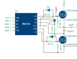
- Are R6,R8 mandatory? It doesn't seems to work properly at low freequency. I expect that when HIN is ON for 100ms, that vgate1 should stay ON for 100ms (time depends on bootstrap cap). But when using 1K R6,R8 gate stays opened for short time as it is drained away very quickly.
- When there is no load, high side MOSFET source is charged from VS and vgate1 compensate so that MOSFET VGS stayes at 0V. Is this expected behavior? If so, I do not like that VCC is leaking into high voltage circuit (bridge). Is there a way to prevent this? I would expect that when IR2110 powers ON and no load is present (all gates in bridge is closed) that all gates should be at 0V and no voltage is present on VOUT1.
ir2110.PNG

Regards,
Boris Makovecki
 

R6 and R8 are shows as 1G not 1K and I would guess they are there for some kind of simulation, they certainly shouldn't be there in normal operation.
The high side of the circuit is powered from the energy stored in the bootstrap capacitor sitting on top of the center point of the MOSFETS so if no signal is being produced it should have little or no drive voltage.

Brian.
 

I've read somewhere that those resistors between source and gate pins of MOSFETs are used to discharge the gate charge faster, so the gate drive waveform is better, and there is smaller risk of shoot-trough time when both MOSFETs are open. Altough, I'd still expect IR2110 to provide a good dead time in order to avoid such issues. Also, you should keep in mind your switching frequency and choose the MOSFETs that are fast enough.
 

I've read somewhere that those resistors between source and gate pins of MOSFETs are used to discharge the gate charge faster
That somewhere is wrong then.
Gate-Soruce pull down resistor is used to avoid parasitic turn on via the Miller capacitance and moreover pulls down the gate to a known state in absence of input signal (if the gate is left "floating").

Discharge the gate faster is achieved with diodes D2 and D5.
 

Hi,

VSS and COM need to be about the same voltage. It is not isolated, it allows only a small voltage between them.
Read datasheet.

VCC and VDD may be driven from different voltages.

Both VCC and VDD need fast capacitors. I recommend to use at least ten times larger than the bootstrap capacitors.
22uF as bootstrap capacitor is only useful with very low PWM frequency.
In most cases a 1uF ceramics is enough.

PCB layout is very important.

Klaus
 

That somewhere is wrong then.
Gate-Soruce pull down resistor is used to avoid parasitic turn on via the Miller capacitance and moreover pulls down the gate to a known state in absence of input signal (if the gate is left "floating").
Curiously, you don't find this resistors in any IR21xx data sheet or application note. When IR2110 is powered, the gates are pulled low by the driver, in unpowered state by the internal substrate diodes. If at all, the resistors may have an effect during slow power ramps if the IR2110 supply voltage is too low to activate the driver, e.g. around 2 to 4 V. But the resistors are usually too weak to prevent parasitic miller turn-on.

In other words, the resistors are an unsubstantiated design idea picked-up somewhere on the internet which doesn't help for 95 percent of applications but may cause serious problems by discharging the bootstrap capacitor too fast.
 
  • Like
Reactions: CataM

    CataM

    Points: 2
    Helpful Answer Positive Rating
Curiously, you don't find this resistors in any IR21xx data sheet or application note. When IR2110 is powered, the gates are pulled low by the driver, in unpowered state by the internal substrate diodes. If at all, the resistors may have an effect during slow power ramps if the IR2110 supply voltage is too low to activate the driver, e.g. around 2 to 4 V. But the resistors are usually too weak to prevent parasitic miller turn-on.

In other words, the resistors are an unsubstantiated design idea picked-up somewhere on the internet which doesn't help for 95 percent of applications but may cause serious problems by discharging the bootstrap capacitor too fast.

I think I've found it somewhere there or similiar site:
http://flyback.org.ru/viewtopic.php...tart=425&sid=e97a566a21ef4d2dfd149e16d69f13f0
37eef33dcc05.jpg
They are also adding extra schottky and fast diodes because "the internal diodes in MOFSETs are too slow".
 

I think I've found it somewhere there or similiar site:

With "application notes", I referred to manufacturers or similarly substantiated papers rather than arbitrary internet publications. I stay with "useless in 95 percent" for the time being.

The substrate diodes topic is somehow beyond the scope of this thread, I think.
 

Don't believe everything you see on the Internet, especially in 'hobby' forums.

The charge path for Cgs is through the series gate resistor, the discharge path is through the same resistor aided by the diode in parallel with it. If the driver voltage is zero (or close to it) and the charge on the gate is holding it above about 0.6V, the diode conducts and dumps more of the charge into the driver. The gate to source resistor plays almost no part in the switching operation but can be fitted as a safety measure if the driver stage is disconnected.

Adding Schottky diodes in series with the drain is silly, it adds the diode storage time to the MOSFET time, making it slower, not faster. Also, consider that overall efficiency depends on the MOSFET rapidly going from 'open circuit' to 'short circuit' and back again, that's the very reason manufacturers strive to make the lowest Rds possible, adding the diode in the drain increases the minimum voltage making it substantially less efficient.

Brian.
 

Last edited:

This substrate diodes

ir2110.jpg

Post #1's schematic comes from the Infineon Designer's example of the H-bridge where they have added the pull-down resistor. Is Infineon mistaken?
Not particularly mistaken, you may use the resistor if you think they are useful and they don't conflict with other design parameters. In this case, the user wants to operate the circuit at a much lower frequency than the 50 kHz assumed in the Infineon tool. He either need to increase the bootstrap capacitor considerably (should use a current limiting series resistor with the bootstrap diode) or omit the pull-down resistor.
 
  • Like
Reactions: CataM

    CataM

    Points: 2
    Helpful Answer Positive Rating
Status
Not open for further replies.

Similar threads

Part and Inventory Search

Welcome to EDABoard.com

Sponsor

Back
Top