Continue to Site

Welcome to EDAboard.com

Welcome to our site! EDAboard.com is an international Electronics Discussion Forum focused on EDA software, circuits, schematics, books, theory, papers, asic, pld, 8051, DSP, Network, RF, Analog Design, PCB, Service Manuals... and a whole lot more! To participate you need to register. Registration is free. Click here to register now.

IGBT Gate current calculation

Status
Not open for further replies.

Bjtpower

Full Member level 5
Joined
Dec 24, 2015
Messages
297
Helped
2
Reputation
4
Reaction score
2
Trophy points
1,298
Activity points
3,893
Hello Friends,

I went through the several threads in this Forum where i did not understood the Gate Current requirement and which driver is to be used.

I am giving you a few details here,

Application: PFC

IGBT USED:https://www.st.com/content/ccc/reso...df/jcr:content/translations/en.DM00079435.pdf

Switching Frequency:20KHZ

Gate drive voltage:15VDC

Total Gate charge from Datasheet:163nC

Now let me know How o calculate the Gate driver current requirement for same.

If traditional methods used, I=Q/T=3.26mA===> Then controller would drive the same because it provide a 20mA of current.

Pls help


Regards
Marx
 

If traditional methods used, I=Q/T=3.26mA===> Then controller would drive the same because it provide a 20mA of current.
You have used cycle time of 50 µs where you should put in Vgs rise/fall time, usually wanted < 1 us.
 

Hi Fvm,

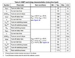
pls check for the attached Image.
Where rise time mentioned here is 17nS.. am i right..??
I=Q/TR=163nC/17nS=9A.. is it..??

- - - Updated - - -

Pls find the attached Image here.


rise time.jpg
 

Current rise and fall time is corresponding to a small part (voltage plateau) of the Qg versus Vge diagram. Total Vge rise/fall time is considerably higher. You should also consider that the Rg of 10 ohm specified in the table is limiting the gate current to 1.5A peak (for 15V unipolar gate drive). So 9A can't ever happen.
 
FVM,

I was analyzing your answer.

I am quite confused if it is depend upon the rise time and Qg.. then what is the use of switching frequency.

Say for 50hz, ppl directly drive it from the Controller.

in our case.. my frequency if i reduced switch frequency to 50 hz then it would

- - - Updated - - -

Can you pls help me on the Same..??
Take my example..
 

To switch the voltage of the IGBT, you need to deliver the whole Qgc (gate collector) charge, which takes place in the Miller Plateau. From fig 15, it is 100 - 25 (aprox) nC = 75 nC.
The current deliverd from the driver is (15 V - Vplateau) / Rgate = 6/10=0.6 A.
The time which takes to switch the voltage of the Collecter-emitter is the time you take to deliver that charge: Voltage switching time = 75 nC/0.6A = 125 nSeconds.

Apart from the above, you also have the time it takes to reach the threshold voltage and to overdrive the gate which we can omit for the time being.
15 V/10 ohm = 1.5 A is driven just for a very short amount of time when the gate-emitter voltage is 0, so make sure your driver is capable of supplying 1.5 A.
 
Last edited:
Not understood..
What is 0.6 A..??
And 1.5A how.. does it have any relation with 125nS..

- - - Updated - - -

Current rise and fall time is corresponding to a small part (voltage plateau) of the Qg versus Vge diagram. Total Vge rise/fall time is considerably higher. You should also consider that the Rg of 10 ohm specified in the table is limiting the gate current to 1.5A peak (for 15V unipolar gate drive). So 9A can't ever happen.

Can you pls help me to understand
 

To switch the voltage of the IGBT, you need to deliver the whole Qgc (gate collector) charge, which takes place in the Miller Plateau. From fig 15, it is 100 - 25 (aprox) nC = 75 nC.
The current deliverd from the driver is (15 V - Vplateau) / Rgate = 6/10=0.6 A.

This is the required current from Driver..??

The time which takes to switch the voltage of the Collecter-emitter is the time you take to deliver that charge: Voltage switching time = 75 nC/0.6A = 125 nSeconds.
Which time are you telling..??

Apart from the above, you also have the time it takes to reach the threshold voltage and to overdrive the gate which we can omit for the time being.
15 V/10 ohm = 1.5 A is driven just for a very short amount of time when the gate-emitter voltage is 0, so make sure your driver is capable of supplying 1.5 A.

If i reduce Gate resistor to 5 ohm then the current would be 3A

In short.. can you elaborate again to understanding..
 

This is the required current from Driver..??
No. The required current from driver is 1.5 A for a very short amount of time. 0.6 A is taken from the driver just to switch the voltage. You have to search for a driver capable of supplying 1.5 A (if Rg=10 ohms and unipolar drive of 15 V).

Which time are you telling..??
125nSeconds it takes for the IGBT to switch its voltage from Bus voltage to 0 volts.


In short.. can you elaborate again to understanding..
Elaborate what? When switching an IGBT/FET, you have 4 regions witch must take place before the switching operation ends:

First --> move the Vge to the threshold
Second --> switch the current
Third --> switch the voltage
Forth --> overdrive the gate


I have calculated the switch of the voltage.
 
Status
Not open for further replies.

Similar threads

Part and Inventory Search

Welcome to EDABoard.com

Sponsor

Back
Top