Continue to Site

Welcome to EDAboard.com

Welcome to our site! EDAboard.com is an international Electronics Discussion Forum focused on EDA software, circuits, schematics, books, theory, papers, asic, pld, 8051, DSP, Network, RF, Analog Design, PCB, Service Manuals... and a whole lot more! To participate you need to register. Registration is free. Click here to register now.

Overload voltage of 1206 resistor and damage to resistor

Status
Not open for further replies.
T

treez

Guest
Hello,
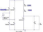
The 1206 SMD resistors in the attached R/Zener regulator will both have a voltage of some 350V across them during mains transients. Will they be able to survive this?... after all, the overload voltage for a 1206 resistor is 400V.
We could add a SMCJ440A TVS, but these suffer a clamp voltage rise up to 713V during their transient clamping.

SMCJ440A TVS datasheet:
https://www.littelfuse.com/~/media/...s/littelfuse_tvs_diode_smcj_datasheet.pdf.pdf

schematic and ltspice sim attached
 

Attachments

  • R zener regulator.JPG
    R zener regulator.JPG
    37 KB · Views: 159
  • R ZENER REGULATOR.TXT
    1.9 KB · Views: 46

Peak Voltage 373V and if the diode is 10V Zener, the current is approximately 0.386mA and each resistor carries 70mW.
1206 Resistors have 0.125W Power Dissipation capability but there is one thing missing here..
Electrical Safety distance is too short due to small footprint of 1206.I think a high voltage type resistor should be used or 1/4W axial type Metal Film resistor will be a better choice.
 

Thanks, the 1206's dont breach an isolation barrier, so why is the distance of the two 1206's not enough?
 

Thanks, the 1206's dont breach an isolation barrier, so why is the distance of the two 1206's not enough?

Between "Any Live Point" and GND/Notr distance should be at least 6mm-If I remember correctly- otherwise this high tension may jump/spark to the other side and it blows everything.
Because the tension is approx. 150-200V between each resistor.Don't take this risk..
 
Thanks, we have live and neutral pads on our PCB which are 2mm apart. They are for hand soldering X2 capacitors in.
I had always taken it that between DC bus positive and negative , 2mm spacing is needed.....but indeed this is just hearsay from various companies.....ive never seen it written down.
Ive been to planty of places where a TO220 transistor has been mounted with non bent pins, and the distance from drain pad copper to source pad copper (which can be 800V+ in say a flyback) is no more than 0.5mm.
-Nobody ever says anything about this kind of thing.
Do you know what is the legal distance between conductors with 300v+ between them on the primary side of an SMPS?.....Its not written anywhere...at least not anywhere that you dont have to pay an arm and a leg to get the info.

- - - Updated - - -

Page 9 of this...
https://www.alternatezone.com/electronics/files/PCBDesignTutorialRevA.pdf

...says 2.5mm is needed between pads which have 300-500v between them, but the standard (if any) from which this arises is not known.

- - - Updated - - -

When reverse engineering OTS offline PSUs, ive seen loads of (non conformal coated) offline flybacks with less than 0.5mm between drain and source copper of a flyback SMPS....due to the TO220 main FET being mounted with the pins "in a line".
It makes you wonder if this is some very loose standard, that nobody really cares about? I mean, we always try and get 2.5mm minimum, but sometimes one is space constrained......there is after all some solder resist between the copper.

Are there suited standards officials opening up power supplies and measuring the distances?
And if there is a danger of a short, then there is always a fuse in the line....so does anyone care?

- - - Updated - - -

In UK I’ve seen tons of domestic , non-isolated, offline led drivers where the leds are mounted on MCPCB, and the MCPCB is screwed to a metal heatsink which comes out to the external surface, where human hands touch. The dielectric distance on MCPCB is in the micrometers……that’s nowhere near 2.5mm.
How are they getting away with it if there is a standard?
Who is checking?
Look on the lightbulb teardowns on youtube and you see loads of these things

- - - Updated - - -

Heres just one of them...mains led bulb with insufficient clearance...
https://www.youtube.com/watch?v=keaE7QTKTYE

- - - Updated - - -

Also, if the “standard” says that there must be 2.5mm clearance between conductors with 300V plus between them, then this 400V rated 0805 size ERJP06 resistor is illegal……
https://www.farnell.com/datasheets/...0.1019522641.1501332265-1679746183.1489787856
…its an 0805 resistor , and is rated for 400V working voltage, and has a spacing between pads of just 1.2mm.
Is it illegal?

- - - Updated - - -

I have always suspected that the standards are only really known to the huge corporations, (they influence the writing of the standards) ...and they are made deliberately opaque and expensive, so that smaller competitors, trying to muscle their way into the market, are sent packing....then we end up with led bulbs with mains live virtually direct to the outer casing...as above youtube shows....that would give a very nasty "bite" if you plugged it in with mains on.
 
Last edited by a moderator:

...otherwise this high tension may jump/spark to the other side and it blows everything....

Approx 10000V (10kV) is needed for a spark or arcing to take place in air with gap of approx 3 mm. (from Wikipedia), 3.4MV is needed for a 1 meter arc. Same source says that the arcing distance for 327V is 7.5um.

Maintaining double the distance (rule of thumb) of the arcing length will keep you safe (I hope)- for 327V, you will need 15um (say 20um as a round figure). For areas where moisture condensation can take place, this values cannot be used.

Please see: https://en.wikipedia.org/wiki/Paschen's_law

(I quoted from here)
 

If you design PCB clearance and creepance distances, refer to safety standards like IEC 1010. In case of doubt, these numbers will be applied if your product requires any approvals.

The working and overvoltage ratings of quoted Panasonic ERJ "anti-surge" resistor series are industry upfront and not achieved by standard resistors.

A PCB which wants to utilize their voltage rating may however need conformal coating, depending on the environmental conditions.
 

Thanks, i just dopwnloaded IEC1010, but it didnt tell of the approved clearance distances.

https://www.google.co.uk/url?sa=t&r...ut.pdf&usg=AFQjCNE6rSDleWca2aEFd3zW_3OLoSqqOw

- - - Updated - - -

The EN61010 costs £316
**broken link removed**
....along with the many thousands of other standards, this is unaffordable. Even when you buy it, it is virtually unreadable....those huge corporations who influenced its writing however, will be assured to know exactly what it really means. They Will have nice conformal products, whilst the small competitors trying to get into the market, will be left way behind.
 

The basic safety standard is IEC1010-1 rather than IEC1010-2.

The clearance and creepage specifications are listed in many other standards, and I presume also in electronic design text books.
 

I cannot seem to download a copy of IEC1010-1.
I wonder what is the clearance distance for copper in the AC section of an offline SMPS?
 

I wonder what is the clearance distance for copper in the AC section of an offline SMPS?

The correct answer is I do not know but I can confidently say that none of the SMPS units used in the common desktop PC will muster the standard.

Even the input output isolation test will fail because of capacitative and inductive couplings.

They were designed, I guess, by the military men for whom cost was not an issue.
 

none of the SMPS units used in the common desktop PC will muster the standard.
Thanks, seriously, PC power supplies all fail standards?..how do they get through the EU customs?
 

I wonder what is the clearance distance for copper in the AC section of an offline SMPS?
What are you asking exactly? Clearance of which circuit nodes?

It seems to me that the thread is drifting towards pure speculation.
 
  • Like
Reactions: treez

    T

    Points: 2
    Helpful Answer Positive Rating
we have two copper pads for manual soldering of an x2 capacitor. The bare copper of each pad is 2mm apart.
The pads occur just downstream of the fuse, but before the bridge rectifier.
Is 2mm ok here?
 

Working voltage 300 V, basic insulation, overvoltage category II needs 1.5 mm clearance on PCB.
 
  • Like
Reactions: treez

    T

    Points: 2
    Helpful Answer Positive Rating
Status
Not open for further replies.

Similar threads

Part and Inventory Search

Welcome to EDABoard.com

Sponsor

Back
Top