CataM
Advanced Member level 4
- Joined
- Dec 23, 2015
- Messages
- 1,275
- Helped
- 314
- Reputation
- 628
- Reaction score
- 312
- Trophy points
- 83
- Location
- Madrid, Spain
- Activity points
- 8,409
Hello everyone,
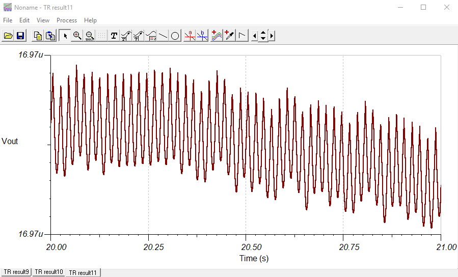
I am trying to simulate a Buck Converter which uses the UCC28710 controller in OrCAD Pspice but it is not working. Not working means it shows an output voltage of micro volts, instead of 12 V.
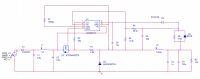
The circuit schematic given by TI is attached.
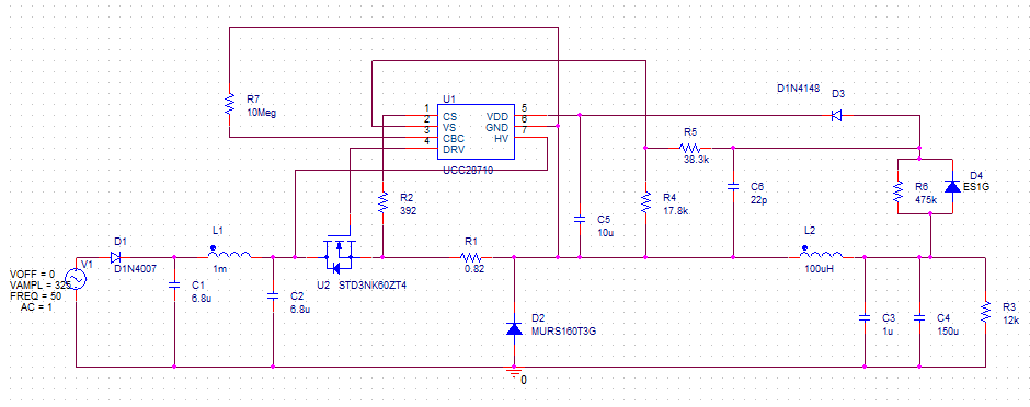
My schematic in order to simulate it is below. I have connected the CBC pin via 10 Meg Ohm resistor to GND pin because it is not possible to let it floating.
I also attached all the parts needed in order to do the simulation in the zip called "additional parts" if someone wants to try it out. It includes the following:
Can anyone help me make the simulation work ?
Thank you for your time !
I am trying to simulate a Buck Converter which uses the UCC28710 controller in OrCAD Pspice but it is not working. Not working means it shows an output voltage of micro volts, instead of 12 V.
The circuit schematic given by TI is attached.
My schematic in order to simulate it is below. I have connected the CBC pin via 10 Meg Ohm resistor to GND pin because it is not possible to let it floating.
I also attached all the parts needed in order to do the simulation in the zip called "additional parts" if someone wants to try it out. It includes the following:
- UCC28710
- ES1G diode (could not find ES1J)
- std3nk60zt4 MOSFET
Can anyone help me make the simulation work ?
Thank you for your time !