Continue to Site

Welcome to EDAboard.com

Welcome to our site! EDAboard.com is an international Electronics Discussion Forum focused on EDA software, circuits, schematics, books, theory, papers, asic, pld, 8051, DSP, Network, RF, Analog Design, PCB, Service Manuals... and a whole lot more! To participate you need to register. Registration is free. Click here to register now.

PIC16F877A with GSM SIM900A interfacing problems

Status
Not open for further replies.

Ngoroka

Junior Member level 1
Joined
Apr 29, 2017
Messages
15
Helped
1
Reputation
2
Reaction score
1
Trophy points
3
Activity points
150
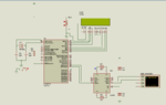
I had designed a project that involves the serial communication between GSM and PIC. But I faced the problem of communication, Initially I used MAX232 to change the level of voltage from 5V of PIC to 3v of GSM but nothing detected from pic to GSM and vice versa, I tried to connect directly without MAX232 but still the problem persisted, then I decided to checkup using Hyperterminal, Both PIC and GSM seems to be okay and communicated fine with PC using FTDI breakout board. so what is wrong with this interfacing.
 

Post the circuit and code and then I will tell you what is the problem.
 

You flipped the RX and TX? You are using the same baud rate? (Just basic questions for serial.)

The MAX232 is not the correct level converter. That is meant to convert TTL to RS232 voltages.

Does the SIM900A run at 3v?
 

Post the circuit and code and then I will tell you what is the problem.

GSM.PNG
here is the circuit that was initially configured.

and below is the code to send sms to the host which was written in MPLAB XC8 compiler
Code:
   UART_Write_Text("AT+CMGF=1\n\r");
              __delay_ms(100);
              UART_Write_Text("AT+CMGS=\"+mobile number\"\n\r");
              __delay_ms(100);
              UART_Write_Text("required sms\n\r");
              __delay_ms(100);
              UART_Write(26); //initially it was written " UART_Write_Text("0x1A\n\r");" then changed to "UART_Write(0x1A)"
              __delay_ms(5000);
              tm++;
                      if(tm>=4){
                       UART_Write_Text("ATD+255753399169;");
                       tm=0;
                      }

As you can see two different connections in MAX232 I tried both connections without success
 

Attachments

  • GSM2.PNG
    GSM2.PNG
    27 KB · Views: 90

As mentioned above, the MAX232 is not the correct level shifter chip. Check out any data sheet for any of the manufacturers of that (or equivalent) chip and you will see that the typical voltage for the T1IN and R1OUT (same for T2IN and R2OUT) is 0 to 5V so that is fine.
However look at the voltages for the other side an you will see they are +/- 5 to 7 volts - do you REALLY want to sent -7V to the GSM chip?
I Googled "5v to 3.3v level shifter" and got back many references to ICs and circuits. In your case you can use the simpler designs as you are not looking for bidirectional level shifting.
Susan
 

As mentioned above, the MAX232 is not the correct level shifter chip.
Susan

I decided to use the diode configuration so that I can reduce the voltage by forward voltage of the diode.diode_shifter.PNG
from the data sheet of 1n4007 diode the forward voltage is 1.1v so for two series diode total forward voltage is 2.2V so the terminal voltage to the GSM becomes 2.8V which is within the range of GSM votages.

But this configuration didn't work with GSM, though it works fine with Hyperterminal of the PC data flows fine to the PC and were monitored to the hyperterminal. someone can doubt may be the diode are reverse biased so they block the flow of data, but unfortunately when I decided to forward biased it didn't work with hyperterminal, it works fine to the hyperterminal when reverse biased.

Furthermore something is crackling my head, GSM don't work with PIC with some reasons of voltage levels, while the same GSM works fine with 5V FTDI breakout board which I used to interface between GSM modem and my laptop (PC) so that I can monitor the data to the hyperterminal, and the same PIC I interfaced with the same FTDI to the PC also works fine. both of them PIC and FTDI have the same voltage levels but why not working with PIC.
 

The datasheet mentions that module wants TTL levels, not RS232 levels. So you should remove the MAX232 from the circuit and replace it with TTL-CMOS level converters.
 

The datasheet mentions that module wants TTL levels, not RS232 levels. So you should remove the MAX232 from the circuit and replace it with TTL-CMOS level converters.

and what is the best TTL-CMOS level converter to be used with PIC16F877A?
but I have worked with ATMEGA328p-PU also its logic voltage is 5V but it works fine with GSM SIM900A , so what causes not to work with PIC?
 
The schematic you have provided in Post #6 might work for the 5V to 3.3V side of things (i.e. from the PIC to the GSM chip) but how do you expect it to boost the 3.3V to 5V going from the GSM chip to the PIC.
If this is for a commercial design (or a class exercise where you are trying to show that you understand good design) then you need to use a proper level shifter IC. There is nothing special about the PIC so using any level shifter that meets the spec will do.
If you want to do this "on the cheap" for a one-off design then check of using a transistor as part of the voltage step-up.
Taking a wild guess about why the ATMEGA MCU works, I'd say that the voltage level where the ATMEGA detects the '1' is lower than the 3.3V (or whatever) that the GSM chip can drive the signal high. Generally there is no problem going from the higher to the lower voltage (except stressing the lower voltage input gate) as long as the higher voltage device can drive the signal low enough for it to be seen as a '0'. To be clear I do NOT think this is a good way to go but it can work if you are lucks and for a short time.
Susan
 

Status
Not open for further replies.

Similar threads

Part and Inventory Search

Welcome to EDABoard.com

Sponsor

Back
Top