Continue to Site

Welcome to EDAboard.com

Welcome to our site! EDAboard.com is an international Electronics Discussion Forum focused on EDA software, circuits, schematics, books, theory, papers, asic, pld, 8051, DSP, Network, RF, Analog Design, PCB, Service Manuals... and a whole lot more! To participate you need to register. Registration is free. Click here to register now.

Flyback source an magnetic air gap.

Status
Not open for further replies.

julian403

Full Member level 5
Joined
Feb 28, 2014
Messages
254
Helped
1
Reputation
2
Reaction score
1
Trophy points
18
Location
Argentina
Activity points
2,105
I was studying the dc-dc converters because I want to do a flayback voltage source.

Flayback.PNG

That's a circuit which ON Semiconductor gives and does all the calculus but there is something missing and it's the ferrite core.

First of all what I found it that in the flayback's switching source the analize of the transformer is more like a couple inductance. There is a difference between a transformer with a couple inductors? I think there is not. But the ferrite transformer's operation is like this:

1-When the transistor is on there is a current flow througth the primary coil and there is an energy store in the magnetic flux.
2-When the trensistor is off the energy stored in the magnetic flux applies in the secundary, generating a voltage.

I think that differs from the operation of a silicon steel transformer at 60Hz Which do not have an energy store. That's energy storage it's because a magnetic air gap?

For example if we applies the voltage red signal to a simple transformer (steel transformer at 60Hz), \[v(t)= 110 sin ( 2 \pi 60 t) [V]\]

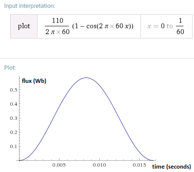
The flux will be: \[\phi = - \frac{1}{n}_{1} \frac{110[V]}{2 \pi 60 [Hz]} cos (2 \pi 60 t) [Wb]\]

and the secundary's voltage will be \[{n}_{2} \frac{d \phi (t)}{dt} = \frac{{n}_{2}}{{n}_{1}} sin (2 \pi 60 t)\]

As we can see there is not difference of phase so there is not energy storage but in the ferrite cores does; if we takes a look here:

https://www.maximintegrated.com/en/app-notes/index.mvp/id/848

And for example, if we see what texas instrument gives. The next graph are the signal for a flayback

Captura2.PNG

from here: https://www.ti.com/lit/an/slva559/slva559.pdf

I do not understand why there is an energy storage, which displays for a difference of phase between the primary and secundary voltages and in a simple transformer at 60Hz do not.
 
Last edited:

Re: Flayback source an magnetic air gap.

The difference between a transformer and a coupled inductor, is that the transformer does not store energy.

**actually, there is a small amount of unwanted energy storage due to fringe fields in a real-world transformer**.

And you are correct, the magnetic energy is stored in the air gap. This is a concept that many times causes confusion to people studying magnetic theory.
 
Re: Flayback source and magnetic air gap.

I thought that the air gap is because there must be an smaller mangetic permeability to can have more ampere-turn. So the energy store is a secundary effect? or is something wanted, too?

Because as a flayback have a dc average value, so the curve is:

imageHvsB.png

So, whit an air gap there is the red curve:

imageHvsB2.png

Which at the point where there is a saturation in the black curve there is not in the red. And what everyone wants is have a transformer which the max B is the saturation (almost saturation as a top) and therefore more oppositive fem in the coil.
 

Re: Flayback source an magnetic air gap.

The B/H curves don't make sense, particularly not the B offset.
 
And for example, if we see what texas instrument gives. The next graph are the signal for a flayback

[...]

from here: https://www.ti.com/lit/an/slva559/slva559.pdf

I do not understand why there is an energy storage, which displays for a difference of phase between the primary and secundary voltages and in a simple transformer at 60Hz do not.
I see nothing wrong with Texas Instruments waveforms and there is no energy storage. The net increment of the flux is 0 as you can see in the current waveforms. Charges up with energy in the first half cycle, and then discharges the energy in the second half cycle (discharges the energy in the secondary load).
 
Charges up with energy in the first half cycle, and then discharges the energy in the second half cycle (discharges the energy in the secondary load).
Yes, but does not happends in a simple transformer, the energy from the first cycle is given in the first cycle. I think you can't see the formula which I wrote in the first post, but if we applies and voltage square waves in the stell transformer's primary there will be an square waves in the secondary with the same phase, without a delay time
 

but if we applies and voltage square waves in the stell transformer's primary there will be an square waves in the secondary with the same phase, without a delay time
Yes, I know. Where is the problem ? The energy stored during the first half cycle is wasted during the second half cycle. The transformer can not store energy because its core would saturate in a short amount of time... that is the reason why always square waves applied to the transformer swing between a positive value and a negative value and not between positive and 0.

- - - Updated - - -

Regarding your calculations of the flux (with sinusoidal voltage), as you can see in the following plot (assuming initial flux=0), the flux rises up and then decreases in order to have a net flux = 0 at the beginning of the next cycle.

I took N1=N2 = 1 turn

- - - Updated - - -

Aaaaaaahhhhhhhhhhh I think I get you know. Just to make sure, please mark in red the phase shift in voltage waveforms you are talking about in post #1 and I will tell you where you got confused. Because seems like you see a voltage phase shift which I do not see :thinker:
 
Captura2.PNG

The red arrow is the primary current and the blue arrow is the secundary current.

Yes, I know. Where is the problem ? The energy stored during the first half cycle is wasted during the second half cycle. The transformer can not store energy because its core would saturate in a short amount of time... that is the reason why always square waves applied to the transformer swing between a positive value and a negative value and not between positive and 0.

The problem is: there is a simple transformer and you applies the signal \[{v}_{1}(t)={V}_{1} sin ( {\omega} t )\] so there will be a flux like this in the core \[ \phi (t)= \frac{1}{{n}_{1}}\int {v}_{1}(t) dt = -
\frac{{V}_{1}}{{n}_{1}{\omega}} cos ( {\omega} t )\] and that generate the next voltage in the secundary \[{v}_{2}(t) = \frac{{n}_{1}}{{n}_{2}} \frac{d \phi(t)}{dt}={V}_{2} sin ( {\omega} t ) = \frac{{n}_{1}}{{n}_{2}} {V}_{1} sin ( {\omega} t )\]. As you can see there is not delay time in the secundary's signal.

I did the calculus with sin signal but if there is a square or pulse signal in primary there will be the same without a delay in the secundary because by fourrier, the armonic (represented by sin signals) do not have a difference of phase. And the signals will have just a difference of amplitude.

So,
The energy stored during the first half cycle is wasted during the second half cycle
That do not happends in a transformer where the energy goes throught the transformer and it's not stored, the only delay there is the speed of light but that's other thing. So, There is another physic phenomen implieted therefore which stored the energy in the first half cycle and wasted during the second half cycle.

I propouse that if there is an air gap, and as the coils (primary and secundary) are in the ferrite material. The flux in the first cycle goes all to the air and not througth the ferrite. And when the primary's ampere-turn goes down the air deliver the energy to ferrite.

So the ferrite's flux would be something like this. \[{\phi}_{f} = \frac{d {\phi}_{a}}{dt}\] where \[{\phi}_{f}\] is the magnetic flux in ferrite and \[{\phi}_{a}\] is the magnetic flux in the air gap. Therefore there will be a delay time in the secondary or a 90º phase difference between the signal in the primary with the secundary.

\[{\phi}_{total} = {\phi}_{f} + {\phi}_{a}\] and \[{\phi}_{f} <<{\phi}_{a}\] so \[{\phi}_{total} = {\phi}_{a}\] and \[{\phi}_{f} = K \frac{d {\phi}_{a}}{dt}\] (where k is a constan which deppends of the permeabilities )because if there is not a derivate in somewhere there can't be energy storage.

Look! I made a simulation with a coupled inductors

look.PNG

There is not delay time
 
Last edited:

As you can see there is not delay time in the secundary's signal.
Yes I know, why would there by a delay ?
Exactly what I thought... You are talking about voltage phase shift but you are showing a current waveform. I knew this was your misunderstanding..just wanted to make sure. Did you have a course in Electrical Machines ?

Look! I made a simulation with a coupled inductors

[..]

There is not delay time
Yes, no delay in voltage waveform but you are talking about the current waveform in the flyback transformer.. you are mixing up current waveform with voltage waveform...
Can you find some voltage waveforms for the flyback transformer and see by yourself that there is no delay in voltage ?
 

Re: Flayback source and magnetic air gap.

I thought that the air gap is because there must be an smaller mangetic permeability to can have more ampere-turn. So the energy store is a secundary effect?

.

Actually, is the other way around.
 
Yes, no delay in voltage waveform but you are talking about the current waveform in the flyback transformer.. you are mixing up current waveform with voltage waveform...
But if there is a resistive load, like the simulation, the voltage has the same form than the current with just a difference in the amplitude and magnitude. And the coupled inductors is just a simple transformer if the air gap do not storage energy.
 

In a flyback transformer (coupled inductor), energy is stored in the transformer inductance as the primary current increases when the primary switch is on.
The switch can be left on until the core nears saturation and no more energy can be stored.
When the primary switch turns off, this inductive current with its energy, is blocked from flowing in the primary path so it flows in the secondary path, transferring the energy to the secondary circuit.
Thus the primary and secondary currents are out of phase.

That is unlike a standard transformer which just transfers the energy from primary to secondary without storing it, thus the primary and secondary waveforms are (must be) in phase.

The transformer air gap is to increase the magnetic flux saturation point of the core material.
The transformer inductance will store energy without the gap but will store more energy with the gap.
This is because the inductive energy is proportional to the current squared but proportional to the inductance^1 (E =½ LI²).
Thus, suppose the air gap reduced the inductance by ½ but allowed an increase in current by a factor of 2 before core saturation.
The net increase in stored energy is then a factor of 2.

- - - Updated - - -

But if there is a resistive load, like the simulation, the voltage has the same form than the current with just a difference in the amplitude and magnitude. And the coupled inductors is just a simple transformer if the air gap do not storage energy.
That's because your simulation is using the transformer as a normal transformer, not as a flyback converter.

A flyback applies a voltage to the primary through a switch and then opens that switch, generating an open circuit on the primary, at which point the energy is transferred to the secondary.
Applying a square-wave to a transformer is not the same thing since the source is never open-circuit but is always a low impedance (zero in the case of your simulation).

So in a flyback converter the output current is always out of phase with the input current for a resistive (or any kind) of load.
 
Ok, let's see if I got it.

The ampere turn in the core is:

\[H = {n}_{1} {I}_{1} + {n}_{2} {I}_{2}\]

to find \[{I}_{1}\] we must look at the primary coil circuit which is a RL's circuit where \[L\] is the primary coil's inductance and \[{R}_{on}\] the transistor chanel's resistance but as the switching conmutation is more faster than the time constant \[{L}_{1}/{R}_{on}\] we can assume:

\[\Delta {I}_{1} = \frac{{V}_{1}}{{L}_{1}} t\]

the same for the secondary circuit:

\[\Delta {I}_{2} = - \frac{{V}_{2}}{{L}_{2}} t\]

So:

\[ \Delta H = {n}_{1} \frac{{V}_{1}}{{L}_{1}} t - {n}_{2} \frac{{V}_{2}}{{L}_{2}} t \]


\[{H}_{max} = {n}_{1} \frac{{V}_{1}}{{L}_{1}} DT - {n}_{2} \frac{{V}_{2}}{{L}_{2}} DT \]

D is the cycle dutty


and in DT the transistor turn off but there is still an magnetomotive force Hmax

\[
H = n I \] so \[{I}_{2}^{0} = \frac{{H}_{max}}{{n}_{2}}\]

\[ {I}_{2}^{0} = \frac{{n}_{1}}{{n}_{2}} \frac{{V}_{1}}{{L}_{1}} DT - \frac{{V}_{2}}{{L}_{2}} DT \]

and as \[{V}_{2} = \frac{{n}_{1}}{{n}_{2}} {V}_{1}\]

\[{I}_{2}^{0} = \frac{{n}_{1}}{{n}_{2}} {V}_{1} DT (\frac{1}{{L}_{1}} - \frac{1}{{L}_{2}})
\]

The complete equation for the secundary circuit is:

\[0 = {L}_{2} \frac{d{i}_{2}(t)}{dt} + {L}_{2} {I}^{0} + {i}_{2}(t){R}_{L}\]

\[{i}_{2}(t) = {I}^{0} {e}^{\frac{{R}_{L}}{{L}_{2}} t}\]

\[{i}_{2}(t) = \frac{{n}_{1}}{{n}_{2}} {V}_{1} DT (\frac{1}{{L}_{1}} - \frac{1}{{L}_{2}}) {e}^{- \frac{{R}_{L}}{{L}_{2}} t}\]

so:

\[{i}_{2}(t) =\frac{{n}_{1}}{{n}_{2}} {V}_{1} DT (\frac{1}{{L}_{1}} - \frac{1}{{L}_{2}} ) {e}^{- \frac{{R}_{L}}{{L}_{2}} t}\]

That would be the solution, where the current I2 takes places from the time DT And as every power electronic circuit such as a simple DC-DC converter there is a succesion of transistors until reaching a premanent state.

What do you think?
 
Last edited:

Sorry, but I seldom get involved in looking at math equations unless I have to.
This doesn't qualify as one of those times. ;-)
 

Sorry, but I seldom get involved in looking at math equations unless I have to.
This doesn't qualify as one of those times.
I must concede that the ways to present a theoretical problem can be different. But in this case, I have serious difficulties to understand which problem julian403 is exactly talking about. I'm missing any reference to commonly used coupled inductor equivalent circuits.

I see that the original post is asking about the relation of forward (direct inductive coupling) and flyback (inductive coupling with intermediate energy storage in main inductance) principle in DC/DC converters.

My general answer is that all transformers can be modeled by a combination of main and leakage inductance, the difference between transformers dedicated for forward and flyback operation is the ratio of both parameters. Other parameters like windings resistance, core losses and nonlinear core characteristic can be considered in the analysis, but you can ignore it at first.
 
Status
Not open for further replies.

Part and Inventory Search

Welcome to EDABoard.com

Sponsor

Back
Top