Continue to Site

Welcome to EDAboard.com

Welcome to our site! EDAboard.com is an international Electronics Discussion Forum focused on EDA software, circuits, schematics, books, theory, papers, asic, pld, 8051, DSP, Network, RF, Analog Design, PCB, Service Manuals... and a whole lot more! To participate you need to register. Registration is free. Click here to register now.

[SOLVED] Why does series inductor at GPS LNA input improve sensitivity?

Status
Not open for further replies.

criterion456

Member level 2
Joined
Sep 13, 2015
Messages
50
Helped
6
Reputation
12
Reaction score
6
Trophy points
1,298
Activity points
2,022
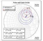
BGA231L7 of Infineon

image002.jpg
image004.jpg


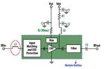
ALM-2412 of AVAGO

image006.jpg
image008.jpg


As shown above, obviously, the series inductor at LNA input is Input Matching to achieve minimum noise figure, thereby improving sensitivity.


Nevertheless, the inductor value is 6.8nH and has 1.8dB insertion loss@ GPS frequency.

image010.jpg


That’s to say,

image012.png


The inductor can increase insertion loss 1.8dB and reduce noise figure simultaneously.

Therefore, there will be 3 possible situations:

1. Noise figure reduces more than 1.8dB : The sensitivity improves.
2. Noise figure just reduces 1.8dB : The sensitivity remains the same.
3. Noise figure reduces less than 1.8dB : The sensitivity aggravates.


But, according to my previous experience, the sensitivity always improves.


So, I’m confused.
Does the series inductor always reduce noise figure more than its insertion loss ?
If not, why does the inductor be still able to improve sensitivity ?


Thanks a lot~!!
 

I think the 1.8dB insertion loss is only true for 50 Ohm source and 50 Ohm load, where the series L causes mismatch. But here, where the L is added for a good reason, only losses (dissipation) from the inductor's series resistance would cause us trouble.
 
Why do you think that 6.8nH series inductor will increase the "Insertion Loss" ?? OK, there will be a small insertion loss due to this inductor but not 1.8dB.
I believe you have confused Insertion Loss and Gain Reduction because of Noise Matching and Gav Matching.The difference can be 1.8dB between Noise Matching and Gav Matching but it doesn't mean the 1.8dB will be inserted between input and LNA.


Hi,

Thanks for your reply. My thought is as below:


1. According to Friis formula :

image001.jpg


For the total noise figure of RX path,
the individual noise figure of these stages posterior to LNA can be ignored because they have gain in their denominator.

For example :

image003.png


The RX path has 4 stages

Stage1 : NF = 1dB, Gain = -1 dB
Stage2 : NF = 0.85dB, Gain = 16 dB
Stage3 : NF = 1dB, Gain = -1 dB
Stage4 : NF = 2.6dB, Gain = 64 dB


Thus, its RX path total noise figure = 1.97(dB)

image005.jpg


Nevertheless, if we just add the noise figure of stage1 and stage2 together:

1dB + 0.85dB = 1.85 dB

The result approximates the previous calculation (1.97dB)

Thus, if the gain of LNA is large enough,

RX path total noise figure = total insertion loss prior to LNA + LNA noise figure


As for your question:

Why do you think that 6.8nH series inductor will increase the "Insertion Loss" ?

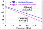
1. Due to the character of the 6.8nH inductor itself, it has about 1.9 dB insertion loss@ GPS frequency(1575 MHz).

Ideal Model Simulation : 1.679 dB
Actual Model Measurement : 1.962 dB

image007.png


2. Because the series inductor is at LNA input,

image009.png


As mentioned above,

RX path total noise figure = total insertion loss prior to LNA + LNA noise figure

Thus, its 1.9dB insertion loss increases RX path total noise figure 1.9dB as well.


3. Indeed, the series inductor can reduce the noise figure of LNA.
Again, as mentioned above,

RX path total noise figure = total insertion loss prior to LNA + LNA noise figure

Thus, RX path total noise figure reduces as well.


4. According to point2 and point3, we know that the series inductor can increase and reduce RX path total noise figure simultaneously.

image011.png

As a result, if sensitivity improves,
the noise figure of LNA must reduce more than the insertion loss of the series inductor at LNA input.

For example:

Insertion loss = 1.9dB, LNA noise figure reduces 2dB => Sensitivity improves 0.1dB
(1.9 – 2 = -0.1, it means that total noise figure reduces 0.1dB)

Otherwise, the sensitivity degrades.

For example:

Insertion loss = 1.9dB, LNA noise figure reduces 1dB => Sensitivity degrades 0.9dB
(1.9 – 1 = 0.9, it means that total noise figure increases 0.9dB)


Is my thought incorrect?
If yes, what’s the blind spot?


Thanks a lot~!!
 

How can you claim 1.8 dB insertion loss caused by the series inductor without ever referring to LNA input impedance respectively S11?
 
RX path total noise figure = total insertion loss prior to LNA + LNA noise figure
Thus, its 1.9dB insertion loss increases RX path total noise figure 1.9dB as well.

According to my RF noise analysis textbook, this "noise figure = insertion loss" passive device math is only valid if the 2-port is matched at both input and output.
 
Last edited:
Hi,

As for your question:

Why do you think that 6.8nH series inductor will increase the "Insertion Loss" ?

1. Due to the character of the 6.8nH inductor itself, it has about 1.9 dB insertion loss@ GPS frequency(1575 MHz).

Ideal Model Simulation : 1.679 dB
Actual Model Measurement : 1.962 dB

View attachment 138430

Is my thought incorrect?
If yes, what’s the blind spot?


Thanks a lot~!!

Dear Critereon456,

You confuse "Mismatch Loss" and "Insertion Loss".

The loss which is coming from the inductor above is a "Mismatch Loss" due to mismatching between the ports due to inserted coil between the ports.Because Input Impedance that is seen from a port is different than system characteristic impedance and of course there is a reflection, so if the energy is reflected, there will absolutely a loss.
An ideal coil ( zero internal resistor) never contributes into noise of a system even its value is gigahenry..
The non-ideal coils have a small series resistance and only this resistance contributes into Noise Figure of a system.Therefore you confuse two losses.

Thanks your detailed reply.
I know what the blind spot is.
:-o
 

Status
Not open for further replies.

Similar threads

Part and Inventory Search

Welcome to EDABoard.com

Sponsor

Back
Top