Continue to Site

Welcome to EDAboard.com

Welcome to our site! EDAboard.com is an international Electronics Discussion Forum focused on EDA software, circuits, schematics, books, theory, papers, asic, pld, 8051, DSP, Network, RF, Analog Design, PCB, Service Manuals... and a whole lot more! To participate you need to register. Registration is free. Click here to register now.

[SOLVED] Strange problem with a switching regulator

Status
Not open for further replies.

flote21

Advanced Member level 1
Joined
Jan 22, 2014
Messages
411
Helped
1
Reputation
2
Reaction score
3
Trophy points
1,298
Activity points
5,595
Hello Folks

I am running out of ideas. I have designed a PCB with three Traco Power switching regulators: TSR1 2450. After an initial test with the three SW Regulators mounted, the PCB was broken because an overcurrent. Then I isolated one SW regulator in a Protoboard (see Pic1) and the SW regulator regulated the voltage rightly (Vin=10V, Vout=5V).
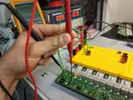
pic1.jpg

However when I mounted again the same regulator on the board (see Pic 2), the SW regulator did not work properly and I measured the output voltage and it was the same voltage (aprox.) like the input voltage (Vin=10V, Vout=9.6V). It is like the regulator short circuits the input with the output. Anyone has any idea about what can it be happening?.
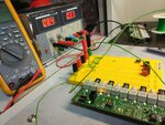
pic2.jpg

Thanks in advance.
 

Sounds like a wiring problem but there is also a a chance that the regulators are going unstable because of the long and thin wires you are using to power them.

At very least, add a capacitor of say 10uF across the inputs of the regulators CLOSE TO THE REGULATOR BODY and maybe a second one by the regulator output pins.

Damaging a PCB by overcurrent sounds like a serious design deficiency!

Brian.
 

Hi!! thanks for you qucik answer.

I would say that it is not a wiring problem because the regultaor mounted on the yellow board works perfectly without any cap indeed and with the green wires connected to the PCB pads. However the same regulator mounted directly on the PCB pads is not working and it looks that it had a shot-circuit between the input and the output....

Very strange....Could it be that the regulator has a protection mechanism or something like that??


Sounds like a wiring problem but there is also a a chance that the regulators are going unstable because of the long and thin wires you are using to power them.

At very least, add a capacitor of say 10uF across the inputs of the regulators CLOSE TO THE REGULATOR BODY and maybe a second one by the regulator output pins.

Damaging a PCB by overcurrent sounds like a serious design deficiency!

Brian.
 

Did you check the board thoroughly after it developed a problem? Why did the original problem occurred in the first place?

Most likely the board has become defective and some other component at a different location is responsible for the head ache.

Try to locate some component that is getting hot...
 

Seems like some component issue or connection problem. can you please cross verify your connections once again If that is fine then try to identify the component which you are using on the PCB not using on the yellow board and check for any component problem. Hope this could solve your problem
 

I figure out that there is a problem with the impedance of the power planes:

Pic1 with the yellow board: Z(24V-GND) = 100K. Notice that there is not short circuit but the Impedance is very low...
Pic2 without the yellow board and the SW regulator mounted directly on the PCB: Z(24V-GND) = 200Ohm.

I guess that there is design failure anyway, but I would like to know if there is anyway to increase the plane impedance to solve this problem momentarily and go on with other tests...

thanks in advance.
 

Just last week, I blew up a perfectly good PSU module when it was installed on the board.
Upon removal of module, I noticed a *very small* dendrite running from the output (170 V) to the adjustment terminal.

Thoroughly cleaning the dendrite and replacing the PSU with a good one, completely fixed the problem.

I'm not saying that your problem is identical to mine. Rather, that these very weird failures sometimes are related to board or solder defects.

This is not the first time it has happened to me. Once I had sensor which was giving intermittent results. To make a long story short, I found that by pushing the board in certain areas, the problem would come and go. It turns out that the board had an intermittent via.

I've several stories like these. And don't get me started on soldering issues of leadless IC packages!!
 

The SW regulator was mounted in the wrong way on the PCB and there was a mess because that....Begginer failure :-( Now it works perfectly :)

Greetings!!
 

... Rather, that these very weird failures sometimes are related to board or solder defects..

IMHO, most of the problems are related to board and solder defects. In many cases, these are the first to cause component failures...

- - - Updated - - -

....Begginer failure :-( Now it works perfectly :)

Who says education is cheap??
 

Status
Not open for further replies.

Similar threads

Part and Inventory Search

Welcome to EDABoard.com

Sponsor

Back
Top