Welcome to our site! EDAboard.com is an international Electronics Discussion Forum focused on EDA software, circuits, schematics, books, theory, papers, asic, pld, 8051, DSP, Network, RF, Analog Design, PCB, Service Manuals... and a whole lot more! To participate you need to register. Registration is free. Click here to register now.
Hello,
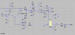
I need to be able to run my circuit for about 50 ms but it shows that the "time step is too small" in LTspice. I tried changing the "Solver" in tools to "alternate" but it works only for 1 ms.
The error can occur in simulation circuits with strong non-linearity, tuning of SPICE transient analysis parameters might fix it. In this case, I guess it's the odd circuit. The combination of U7 used as comparator and D1 connected to non-terminated multiplier input looks flawed.
There much simpler ways to make a +/-1 or 0/1 multiplier.
Those ideal amplifiers / comparators may default to absurd
edge rates. And vendor macromodels are often full of icky
controlled sources that act differently in one simulator than
the next (B sources, and model defaults, are inconsistent).
ADI macros I have seen mention ngspice and PSpice as
having been checked / validated, but not LTSpice (and
I am having bad outcomes in yet another SPICE variant
at present - factor of 100 off, in AC and transient analysis
- on an ADI macromodel that -does- work well in LTSpice).
If you can change METHOD to GEAR maybe things will
work out better - TRAP tends to overshoot and take nodes
/ currents to insane positions (even when "converged")
which can blow things up in ways you would not imagine,
and all you get for debug guidance is "fail". Although an
attempt to print transient operating points and node
voltages at the fail endpoint could narrow down the
bit of circuitry involved, somewhat. Good luck with that,
probably a deep dive in the documents to find how (or
if even possible) to get it.
The "tran" command is only partially filled in. The "Maximum timestep" must be a certain amount of time but it is blank. The "Time to start saving data" is also blank.l
LTSpice seems to tolerate this, I've seen sims run OK
with only ".tran 5m". But another (I'm straddling) fails
right off the bat if you don't give it the timestep
(".tran 10n 5m"). Just another dialect / defaults difference.
Now allowing timestep to get too large -can- get you
into trouble, your timestep should be constrained to
less than the narrowest pulse width that could be
applied or created in the circuit.
Yes, I've found that any behavioral block that you have
not proven to be well behaved, should have small series
resistors between its terminals and the rest of the schematic.
Depending on how behavioral models are treated, direct
connection to "code" can act really weird.
This site uses cookies to help personalise content, tailor your experience and to keep you logged in if you register.
By continuing to use this site, you are consenting to our use of cookies.