T
treez
Guest
Hello,
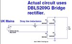
Do you know what is the reverse recovery time (trr) of the diodes in the DBLS209G mains rectifier bridge?
If it were connected in a circuit as in the attached (LTspice sim also attached), then would you expect to see much of a reverse recovery “snap-off” of the reverse current?
…..By this, I mean as described here by Power.com...............................
(i presume the slow reduction to zero current and commutation at the mains zero cross means that reverse recovery "snap off" will be very minimal?...thus the recomendations of power.com will not be relevant to us?)
EMC problem due to slow diodes in mains rectifier…..
**broken link removed**
DBLS209G Rectifier bridge datasheet
https://www.mouser.com/ds/2/395/DBLS201G SERIES_H13-523528.pdf