Continue to Site

Welcome to EDAboard.com

Welcome to our site! EDAboard.com is an international Electronics Discussion Forum focused on EDA software, circuits, schematics, books, theory, papers, asic, pld, 8051, DSP, Network, RF, Analog Design, PCB, Service Manuals... and a whole lot more! To participate you need to register. Registration is free. Click here to register now.

Cheap mains conducted emissions tester?

Status
Not open for further replies.
T

treez

Guest
Hello,
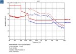
Our direct drive 100W offline, non-isolated LED driver failed EMC as attached.
We need to re-test it ourselves.
Do you know the cheapest LISN and spectrum analyser that we can buy to repeat the test? Its too expensive to keep going back to the test house.

Our led driver is 86% efficient but is not SMPS based...its just led banks that get switched in and out as the mains rises and falls after the mains rectifier bridge.
The di/dt is very low.
We are amazed we have failed conducted emissions this badly.
 

Attachments

  • EMC scan conducted emissions.jpg
    EMC scan conducted emissions.jpg
    84.3 KB · Views: 184

This DSA815 spectrum analyser looks like being the cheapest spectrum analyser in the world for this job at $1300

Specturm analyser.
https://www.rigolna.com/products/spectrum-analyzers/dsa800/

The problem is we are having difficulty sourcing a cheap LISN to connect up to it.
Do you know of one?

I would have thought there were cheap kits for sale on this because surely everyone needs to do this?...i mean its just too expensive to go to a test house every time.
 

You can buy a cheap LISN like Hameg HM6050, or make it yourself.
 
  • Like
Reactions: treez

    T

    Points: 2
    Helpful Answer Positive Rating
Thanks, the Hameg HM6050 looks good but doesnt say if it has facility to be bolted to a ground plane. As you know, simple wire connection to the ground plane is unacceptable for conducted emc testing, because it would be too high impednace at the higher frequencies. Then again, we only want to go up to 30MHz so i am kind of wondering why it has to be bolted for that, i mean, 30MHz is hardly microwave frequency.

Hameg HM6050
https://www.farnell.com/datasheets/1851611.pdf?_ga=1.216594710.1679746183.1489787856

We also wonder where we would put the metal sheet ground plane to ensure it is a low impedance to earth. I presume we would have to connect it near the main earth wire input connection to our building....after all, if the metal ground plane on which the emc test is carried out doesnt have a really low impedance to earth, then this will compromise the results. As you know, the metal sheet ground plane cannot simply be wired to an earth point in a mains plug.

It also begs the question of what type of mud our factory is built on...because if the foundations have a high impedance to earth, then again, our conducted emc test results will be compromised, because a really low impedance to earth is needed for the conducted emc test. Do you know how we ensure the low impedance to earth?

Also, 4:07 onwards of this video shows that as well as a LISN, we will need a transient protector, a filter/selector, and a pre-amplifier leading up to the spectrum analyser. I hope the HM6050 will have these things incorporated into it?
EMC video
https://www.youtube.com/watch?v=oXxmmckm5sI
 
Last edited by a moderator:

I didn't yet bother with CISPR16-1-2 measurement specification details, and don't apply to do now. Respectively I can't say under which conditions HM6050 can be used, or if it possibly needs to be supplemented or modified.

But you possibly realize what's the test houses job is in this regard.

My feeling is that the ground plane won't change the conducted emissions up to 30 MHz of a small device so much, you can make an estimation of common and differential mode impedances to check yourself.
 

we will need a transient protector

We use the Hameg box, and it has a transient limiter, but no pre-amp.
 

Thanks,
We wish to make our own cheap Conducted Emissions test kit for our 50-250W UK mains powered LED luminaires. We don’t need perfection. We are trying to make a LISN. The inductor in the LISN is to be 50uH. This inductor is supposed to be air core, made by hand winding over plastic drum . The inductor should feature damping resistance along the coils to reduce ringing due to the inductors self resonant frequency. However, if we just pick say an inductor with a SRF of about 7MHz, then does that mean that our readings of conducted emissions will be OK up to around 5MHz? Also, suppose we want an increased SRF, then can we just solder in series a load of say 3uH inductors till we get to the 50uH value (then the SRF will be higher)

Making a LISN…
**broken link removed**

At the moment we have picked this inductor...
http://uk.farnell.com/coilcraft/pcv-0-473-05l/inductor-power-47uh-6a-10/dp/2457647

- - - Updated - - -

The LISN diagram of the above link document (page 2) shows an input filter as well as the LISN. Does the input filter have to have these exact component values. (L2 = 250uF and C2 = 4uF)
Also, it says that the L2 inductors are coupled inductors (common mode choke)….but I thought the LISN was also supposed to be able to measure common mode emissions?
Also, for measuring common mode emissions, I presume the kit has to be able to allow measurement of 100MHz plus? Common mode conducted emissions, as I understand it, are rarely prevalent below about 10MHz?
Also, how do you make a LISN that can allow common mode emissions measurement? Do you have to use a coupling network out of coupled coils?
Also, presumably there are problems when measuring common mode emissions because the signal level will be extremely low….so I presume some kind of broadband RF amplifier will be needed for its measurement?

Also, if we dont make it in a metal box, (instead use plastic) then to what frequency will the LISN be effective up to?
 

Unfortunately there's no SRF specification for the inductors. Preferably you'll verify the LISN impedance and transfer function above 1 MHz with a network analyzer.

But I agree with the consideration that for a emission spectrum as in post #1 the inductor specification isn't so critical.
 

Thanks, the following 47uH inductor has a SRF of 7MHz, so presumbaly this would be no good for use in a LISN that needed to measure above say 5MHz?

http://www.coilcraft.com/pdfs/mss1278t.pdf

We dont have a network analyzer, we just intend to buy a DSA815 spectrum analyser , and then our budget is under strain.

Also, to what frequency will our LISN be good up to, if we dont bother with the earthed metal case, and dont bother to bolt its earthed metal case to a big metal ground plane sheet?
as in the folloiwhng documents recomendations...
http://www.compliance-club.com/archive/keitharmstrong/emc_testing2.html
 
Last edited by a moderator:

If you simplify the LISN specification a bit, it's essential that the DUT termination impedance is constantly 50 ohm above 1 MHz, in other words, that the generated noise is quantitatively coupled to the 50 ohm measurement output respectively passive termination. Inductor self resonance isn't a problem as such, but the capacitive impedance above SRF is if it affects the termination impedance. In so far the idea of connection an additional series inductor isn't bad.
 

the following 47uH inductor has a SRF of 7MHz, so presumbaly this would be no good for use in a LISN that needed to measure above say 5MHz?
For a 47 uH with SRF 7MHz, the assumption that your inductor is an ideal one is valid up to ~4.5 MHz. See the following |Z| graph with respect to frequency.


For a 47 uH with SRF 7MHz, the assumption that your inductor is an ideal one is valid up to ~4.5 MHz. See the following |Z| graph with respect to frequency.
That's true, but 11 pF parallel capacitance changes the impedance magnitude of 50 ohm termination only by about 1 %. So a 50 µH inductor with 7 MHz SRF might be still acceptable for this LISN circuit.
 
  • Like
Reactions: CataM

    CataM

    Points: 2
    Helpful Answer Positive Rating
Thanks,
when you speak of the impedance termination of 50 ohms, do you mean the 50 ohm resistor on the 2nd page of the following...?
**broken link removed**
 

I'm not specifically referring to the DIY schematic, but generally to the CISPR16-1-2 LISN specification. In the said schematic it's either the 50 ohm termination resistor in the bottom path or the 50 ohm EMI receiver input.
 

Thanks, of course i was forgetting, if the spectrum analyser has a 50 ohm input impednace then we then dont need the 50 ohm resistor at the signal output of the LISN?
 

What ever you connect at the receiver output, the total impedance should be near to 50 ohms. Usually you have an attenuator and possibly a limiter to protect the receiver.
 
  • Like
Reactions: treez

    T

    Points: 2
    Helpful Answer Positive Rating
Thanks, do you think the Picoscope 2205A can be conected to th LISN to do testing of conducted emissions?
I am a little concerned that it only has 1 Megaohm input impedance BNC connection ports.

Picoscope 2205A:
https://www.picotech.com/download/datasheets/picoscope-2000-series-data-sheet-en.pdf

- - - Updated - - -

Does a PA1000 Power analyser contain a LISN within itself?..........

Hello,
The Tektronix PA1000 power analyser allows doing mains input current harmonic measurments (up to 50th mains harmonic , ie 2500Hz).
In this case, it must surely contain a LISN within itself? I mean, without a LISN, the mains input current harmonic measurement would be meaningless?
Or is it the case that the lowness of the mains harmonic current frequency means that a LISN is not necessary for measuring them?
Anyway, if a LISN is not necessary to do a Mains input current harmonic measurement, then why bother buying a PA1000, why not just buy a much cheaper $225 Picoscope 2205A and do the mains input current harmonic measurement and power factor measurement with that instead?


Tektronix PA1000 Power Analyser ($2990)
https://www.sjelectronics.co.uk/media/acatalog/PA1000.pdf

Picoscope 2205 Oscilloscpe ($225)
https://www.farnell.com/datasheets/1909241.pdf?_ga=1.118836809.1180190824.1491763050
 

I am a little concerned that it only has 1 Megaohm input impedance BNC connection ports.
Plug a BNC feed-through termination.

- - - Updated - - -

Does a PA1000 Power analyser contain a LISN within itself?...
No. Power quality analysis (EN61000-3-2 etc.) uses completely different test setups than radio interference measurements (CISPR16-1-2 etc.). Guess you have heard about it before.
 
  • Like
Reactions: treez

    T

    Points: 2
    Helpful Answer Positive Rating
Status
Not open for further replies.

Similar threads

Part and Inventory Search

Welcome to EDABoard.com

Sponsor

Back
Top