strahd_von_zarovich
Advanced Member level 4
Hi everybody,
I am trying to design opamp circuits, but I couldn't fully understand how to find input and output impedance of an Opamp circuit.
When the configuration is Non-Inverting, input impedance of the circuit is High-Impedance and for impedance matching I may use a resistor with parallel to opamp +Vin . For example I use the configuration below for 50Ohm input impedance matching. Also, I use serial resistor for output impedance matching because circuit's output impedance is zero I guess :-?

And when the configuration is inverting, circuit's input impedance is Rg right ? So for input impedance matching I must choose Rg appropriately right ? For example, for 50ohm impedance matching, I must choose Rg 50 Ohm right ? Also I find output impedance for this circuit is 0 Ohm, am I right ? :-?
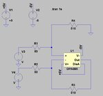
Lastly, I found input impedance of a differential Opamp circuit is 2*Rg. So if my first opamp is AD8015 : https://www.analog.com/media/en/technical-documentation/data-sheets/AD8015.pdf , then for input impedance matching do I have to use something like the below ?

Also for differential opamp circuit, I found output impedance of the circuit is zero ohm. However, I am not sure if my method is true or false.
I am trying to design opamp circuits, but I couldn't fully understand how to find input and output impedance of an Opamp circuit.
When the configuration is Non-Inverting, input impedance of the circuit is High-Impedance and for impedance matching I may use a resistor with parallel to opamp +Vin . For example I use the configuration below for 50Ohm input impedance matching. Also, I use serial resistor for output impedance matching because circuit's output impedance is zero I guess :-?

And when the configuration is inverting, circuit's input impedance is Rg right ? So for input impedance matching I must choose Rg appropriately right ? For example, for 50ohm impedance matching, I must choose Rg 50 Ohm right ? Also I find output impedance for this circuit is 0 Ohm, am I right ? :-?
Lastly, I found input impedance of a differential Opamp circuit is 2*Rg. So if my first opamp is AD8015 : https://www.analog.com/media/en/technical-documentation/data-sheets/AD8015.pdf , then for input impedance matching do I have to use something like the below ?

Also for differential opamp circuit, I found output impedance of the circuit is zero ohm. However, I am not sure if my method is true or false.
