Continue to Site

Welcome to EDAboard.com

Welcome to our site! EDAboard.com is an international Electronics Discussion Forum focused on EDA software, circuits, schematics, books, theory, papers, asic, pld, 8051, DSP, Network, RF, Analog Design, PCB, Service Manuals... and a whole lot more! To participate you need to register. Registration is free. Click here to register now.

[SOLVED] [MOVED] How to Plot Power Graph In Proteus ?

Status
Not open for further replies.

Okada

Banned
Joined
Jun 16, 2016
Messages
1,159
Helped
129
Reputation
252
Reaction score
129
Trophy points
63
Activity points
0
How to Plot Power Graph In Proteus ?

My circuit is a simple half wave rectifier. I have designed the circuit in Proteus and have added graph to display AC voltage and DC voltage but I am not able to add Power trace to graph.

There is a feature called Add Transient Trace but I don't know how to use it.

Can somebody modify my Proteus file and add the power trace to graph. It should show output voltage * output current and also it should show output voltage and output current in the same graph.

What I tries: I added output voltage probe and current probe and added them to graph and then added a trace called P with the expression P1*P2 but it doesn't give power graph.
 

Attachments

  • Rectifiers.rar
    24.5 KB · Views: 83

Ok. I plotted the power graph but graph doesn't show correct value for Iac and Power P. Why ?
P = VI

V is 12Vrms
Vpk = 12 * 1.4142 = 16.9704V (which is correct on the graph)
Rt = 4.4R

Iac(pk) should be V/Rt = 16.9704/4.4 = 3.8569A

Ppk should be Vpk * Ipk = 16.9704 * 3.8569 = 20.82 W
 

Attachments

  • AC Circuits.rar
    93.5 KB · Views: 77

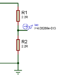
Apparently you are shorting R2 by the current measurement circuit, the I and V numbers suggest an effective load resistor of 2.2 ohms.

Could it be that you simply misunderstand what you have "clicked together" in your Proteus simulation?
 
  • Like
Reactions: Okada

    Okada

    Points: 2
    Helpful Answer Positive Rating
What should I do ? Should I remove the ground connection ? If I remove the ground connection then in Virtual Oscilloscope it shows Vac but in graph current doesn't plot. It remains 0 always.

It is only considering one 2.2R and calculating current. Without ground connection it doesn't plot current.

If one 2.2R is considered then graph data is correct.

I = 12*1.4142/2.2 = 16.9704/2.2 = 7.714A

P = VI = 16.9704 * 7.714 = 130.9W
 
Last edited:

What should I do ?
Learn how the Proteus simulation circuit elements actually work and use it accordingly.

circuit.png

If this circuit acts as 2.2 ohm load because the current meter shorts R2, but you want apparently 4.4 ohm, what's the conclusion?

I'm under the impression that the anti-intuitive Proteus simulation IDE permanently brings up similar confusion...
 
  • Like
Reactions: Okada

    Okada

    Points: 2
    Helpful Answer Positive Rating
If this circuit acts as 2.2 ohm load because the current meter shorts R2, but you want apparently 4.4 ohm, what's the conclusion?

Make R1 = 4.4R.

Edit:

Here are the working projects and simulation results.
 

Attachments

  • AC Circuits.rar
    222.2 KB · Views: 78
  • Half Wave Rectifier.rar
    110.3 KB · Views: 123
Last edited:

Status
Not open for further replies.

Similar threads

Part and Inventory Search

Welcome to EDABoard.com

Sponsor

Back
Top