Continue to Site

Welcome to EDAboard.com

Welcome to our site! EDAboard.com is an international Electronics Discussion Forum focused on EDA software, circuits, schematics, books, theory, papers, asic, pld, 8051, DSP, Network, RF, Analog Design, PCB, Service Manuals... and a whole lot more! To participate you need to register. Registration is free. Click here to register now.

code for counter such that it should count for every 2 positive edges of clock

Status
Not open for further replies.

ecasha

Junior Member level 2
Joined
Feb 28, 2017
Messages
24
Helped
0
Reputation
0
Reaction score
0
Trophy points
1
Activity points
197
How to write verilog code such that output values should change for every 2 clock cycles? I have written code for counter,it is changing/counting for every posedge of clock.I want, it should count after 2 posedge clock .How do i write code?

Code:
 always @ (posedge clk) begin
 if (rst)
  d<= 0;
   else
 d<=d+1;
end
 

Using existing clock 1st build a base_counter that counts 0, then 1, then it wraps to 0 and then again 1, and so on, on the rising edge of clock.

Now increment your counter on the rising edge of clock, only when base_counter value is 1.
There............. you'll have the
code such that output values should change for every 2 clock cycles
.

How do i write code?
If you want to delve into digital design you must write this yourself. It is pretty simple, very fundamental stuff.

In this thread https://www.edaboard.com/threads/365945/ at #3 you have already been advised what you can do to improve.
 
  • Like
Reactions: hcu

    hcu

    Points: 2
    Helpful Answer Positive Rating
Is it not correct use frequency divider?
 

Is it not correct use frequency divider?

Don't use them for real-life designs.
Let the clock remain as it is. Generate clock enable signals from counters to do what you want to do.
 

Is it not correct use frequency divider?

technically, it is correct and doable. in reality, you will create a much bigger headache later. keep it simple, within the same clock domain.
 

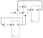
Describe the following circuit in Verilog.
Capture.PNG

The bottom left FF creates a divide by 2 enable.
The top right FFs with the mux implements an enabled FF.
The add by 1 along with the feedback from the enabled FF implements a simple rollover counter.
 
  • Like
Reactions: hcu

    hcu

    Points: 2
    Helpful Answer Positive Rating
Hi,

Use any n bit width counter, but don't use output Q0.
Q1 will toggle with every second rising clock edge.

Klaus
 

Hi,

Use any n bit width counter, but don't use output Q0.
Q1 will toggle with every second rising clock edge.

Klaus
Klaus, I don't think you are answering their original question. What you have described doesn't match what they are trying to do.

The OP wants to write a Verilog counter that counts at half the frequency of the clock.
 

You'll need 2 counters. The first to count from 0 to 1, and the second (which is your main counter), to check if the first counter has counted up to "1". Essentially, the first counter serves as an "enable" for the second one.
 

You'll need 2 counters. The first to count from 0 to 1, and the second (which is your main counter), to check if the first counter has counted up to "1". Essentially, the first counter serves as an "enable" for the second one.

Uh, this was already mentioned in post #2 and drawn in post #6.
 

What problems will arise in the future? Besides the need to correctly declare the generated clocks in the SDC?

think big. if every designer on an SoC is allowed to create a few clocks here and there, the entire system will be much harder to implement and more error prone. keep it simple.
 

Klaus, I don't think you are answering their original question. What you have described doesn't match what they are trying to do.

Maybe I misunderstood...but I don't see it yet..

Doesn't the OP want: output after each positive clock edge:
0-0-1-1-2-2-3-3-4-4-5-5....

Your solution:
First FF:
0-1-0-1-0-1-0-1-0-1..
Counter out:
0-0-1-1-2-2-3-3-4-4...

And what's the difference compared to a binary counter output
Bit 0:
0-1-0-1-0-1-0-1-0-1..
Value of bit1 ...bitn (ignoring bit0)
0-0-1-1-2-2-3-3-4-4...

Klaus
 

I found this interesting and i tried and verified this problem.

Any efficient way of doing this ?? Want to learn more from the top experienced viewers .
Code:
//DUT

`define value 9 //counter increments only after (9 + 1) clocks
module clock_gen(
input clk_in,
input rst,
output reg [`value-1:0] enable,
output reg [3:0] count
    );
always@(posedge clk_in )
begin
if (rst) begin
  count <= 4'd0;
  enable <= 'd0; end
else
  enable <= enable == `value ?  'd0 : enable + 'b01 ;
  if(enable == `value)
    count <= count + 1'b1;
end
endmodule

//testbench
`define value 9
module tb_clkgen;

	// Inputs
	reg clk_in;
	reg rst;

	// Outputs
	wire [`value-1:0] enable;
	wire [3:0] count;

	// Instantiate the Unit Under Test (UUT)
	clock_gen uut (
		.clk_in(clk_in), 
		.rst(rst), 
		.enable(enable), 
		.count(count)
	);

	initial begin
		// Initialize Inputs
		clk_in = 0;
		rst = 1;

		// Wait 100 ns for global reset to finish
		#120;
      rst = 0;
		
		// Add stimulus here

	end
      initial clk_in = 1;
		always #10 clk_in =~clk_in;
endmodule
 
Last edited:

Status
Not open for further replies.

Part and Inventory Search

Welcome to EDABoard.com

Sponsor

Back
Top