Continue to Site

Welcome to EDAboard.com

Welcome to our site! EDAboard.com is an international Electronics Discussion Forum focused on EDA software, circuits, schematics, books, theory, papers, asic, pld, 8051, DSP, Network, RF, Analog Design, PCB, Service Manuals... and a whole lot more! To participate you need to register. Registration is free. Click here to register now.

Need help with generating *INTERLACED* mode VGA signals

Status
Not open for further replies.

whack

Member level 5
Joined
Feb 25, 2006
Messages
81
Helped
3
Reputation
6
Reaction score
3
Trophy points
1,288
Activity points
2,257
Hey all,

I'll try to make it as short as I can. I've got VGA signal generation working on FPGA and I'm playing with a CRT monitor with different resolutions. Now that I've learned how to generate different refresh rates and resolutions, I need to learn how to generate interlaced VGA signal.

What I need help with is explanation if there are any differences in timings compared to normal ("progressive") VGA scan, and what the waveforms for horizontal and vertical sync signals look like. (Signal polarities...?)

I don't require help with VHDL and Verilog code, I need just theory and waveforms. A good diagram from somewhere would be golden.

Information on interlaced VGA modes is scarce on the Internet, because, well, pretty much nobody used them. I did search before I posted.

Help is appreciated. Thanks!
 

VGA does not support interlaced formats.
Are you talking about 480i (NTSC)? 576i (PAL)? 720i (barely used) or 1080i (FULL HD, used in broadcast video)?
 

VGA does not support interlaced formats.
False.
Are you talking about 480i (NTSC)? 576i (PAL)? 720i (barely used) or 1080i (FULL HD, used in broadcast video)?
None of the above.

For a start examine the industry standard 1024x768 43Hz interlaced mode for VGA interface. Then apply the concept for other resolutions (obeying minimum VGA scan ranges). I recommend you subscribe to this thread to learn something new.

http://tinyvga.com/vga-timing/1024x768@43Hz
Unfortunately that info was not enough for me to understand (and perhaps there are errors). There are some things about it I don't understand, like how even/odd fields are shifted in respect to one another. Really need a timing diagram for that. We should wait for someone knowledgeable to explain.
 
Last edited:

Ok - its a new one to me.
But with a little bit of google - you could easily have found out what all this meant:

EG: **broken link removed**
 

Some confusion here.
VGA does have interlaced modes although in it's 30 or so years of existence I don't think I've ever seen it used. VGA is a computer display mode.
576, 720 and 1080 interlaced and progressive scan modes are for broadcast television video and CCTV.

There is some overlap and scan conversions between the two systems but they are basically intended for different purposes.

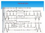
To make a signal 'interlace' add half a line scan to one field and remove half a line from the other. In systems with composite sync it is necessary to add equalizing pulses to prepare the timebases but in VGA where the syncs are carried as an independent signal, it probably isn't necessary.

Brian.
 

Field group.jpg
See slide 42.
https://www.slideshare.net/MadhumitaTamhane/black-and-white-tv-fundamentals

You will need to alternate between even and odd fields by displacing the horizontal sync half a line with respect to vertical sync.
The reading of your video ram will also need to account for both even and odd line data, as well as this half line displacement between even and odd fields.
If you don't do that you will see two superimposed images shifted by half a line.

This is only going to work on very old analog crt monitors.
Anything even remotely recent will just reject the signal completely, and you will get an on screen message something like "video format not recognised" and a blank screen.

The problem with VGA is there are so many different standards, dozens of them with widely varying field and line rates and resolution. The only way it can work is if a microprocessor measures up the incoming sync waveforms and goes to a lookup table to decide which VGA standard is incoming. If your home made non standard interlaced VGA is not recognised in the lookup table, the monitor will just reject it and show an error message.
If you have maybe a thirty to thirty five year old completely analog crt monitor it might work.
 

Ok - its a new one to me.
But with a little bit of google - you could easily have found out what all this meant:

EG: **broken link removed**
Mmm, yeah. I've seen that. It's probably not useful for VGA, that's a television signal. That diagram is missing at least one crucial detail that differentiates VGA interlaced scan signals from television. Read on.

Some confusion here.
That's okay. Hopefully this thread will clear up any confusion you have. Read on.

VGA does have interlaced modes although in it's 30 or so years of existence I don't think I've ever seen it used. VGA is a computer display mode.
576, 720 and 1080 interlaced and progressive scan modes are for broadcast television video and CCTV.

There is some overlap and scan conversions between the two systems but they are basically intended for different purposes.
Stick to computer monitors. Don't go into television standards please. And no, there's a bit more to it.

To make a signal 'interlace' add half a line scan to one field and remove half a line from the other. In systems with composite sync it is necessary to add equalizing pulses to prepare the timebases but in VGA where the syncs are carried as an independent signal, it probably isn't necessary.
That's the basic idea but lacks important details for implementation.

View attachment 137209
See slide 42.
http://www.slideshare.net/MadhumitaTamhane/black-and-white-tv-fundamentals

You will need to alternate between even and odd fields by displacing the horizontal sync half a line with respect to vertical sync.
The reading of your video ram will also need to account for both even and odd line data, as well as this half line displacement between even and odd fields.
If you don't do that you will see two superimposed images shifted by half a line.
That's a TV signal. We are talking VGA signals here. Shifting by half a horizontal sync is the basic concept for interlace but on VGA signal there are some important implementation details, which the above explanation lacks. Read on.

This is only going to work on very old analog crt monitors.
I'd say you're wrong, but I have to take into account that your definition of "old" might differ from mine. As of the very last generation of CRT monitors, like the year 2000 SVGA monitor I have here, interlaced modes still work as intended.

Warpspeed; said:
Anything even remotely recent will just reject the signal completely, and you will get an on screen message something like "video format not recognised" and a blank screen.
If by recent you mean an LCD monitor, then that would likely be true. If you read my OP you will see that we are talking strictly CRT here. So not really true, false.

The problem with VGA is there are so many different standards, dozens of them with widely varying field and line rates and resolution. The only way it can work is if a microprocessor measures up the incoming sync waveforms and goes to a lookup table to decide which VGA standard is incoming.
True.

If your home made non standard interlaced VGA is not recognised in the lookup table, the monitor will just reject it and show an error message.
Then we should stick with standard interlaced modes. No need to invent anything yet. Read on.

If you have maybe a thirty to thirty five year old completely analog crt monitor it might work.
False.

-------------------------------------------------------------

Okay, so clearly I'm not the most confused person on this thread, and that's good, because being confused is not what I need.

Let's get some facts out of the way first:
interlaced2.pnginterlaced1.png
I've used these modes over the years. They're not great to use, but we're not trying to break new ground in CRT productivity here. We are just learning to generate signals.
If you have a computer that outputs VGA signals and has at least a half decent video card you will be able to select one of these modes. And if you have a CRT monitor you could even try it.

So since pretty much everybody has this readily available including myself, then there should have been nothing there to stop me from recording the waveforms and implementing them on FPGA, except for one crucial problem. I don't own a good oscilloscope with recording ability to be able to record the scan signals for alternating interlaced fields to make measurements from.

Now, for the one detail you guys seem to have missed so far is the fact that VGA sync signals also have a variable polarity, application of which I don't yet understand. Look here:
http://tinyvga.com/vga-timing
http://tinyvga.com/vga-timing/1024x768@43Hz
http://tinyvga.com/vga-timing/1024x768@70Hz
http://tinyvga.com/vga-timing/1024x768@85Hz
If you look closely, you will notice that some modes use negative sync signals, while others use positive. Looking at a TV signal timing diagram will certainly not be helpful here.

As of this morning I tried shifting horizontal sync by half a scanline time, but the image on the monitor did not show interlacing, monitor seems to have ignored the change in horizontal scan timing of the even field. Something else is needed here as well.

It would really be great to have a complete timing diagram for this. Kind of surprising because the modes were pretty standard.
 

You are clearly the expert here - as no one else seems to have ever heard of it, used it or care about it.
Why are you trying to support this standard?
 

You are clearly the expert here
I don't think that was meant to be a compliment. I'm not an expert, and I don't appreciate being trolled for asking about some obscure but very valid technical question.

as no one else seems to have ever heard of it, used it or care about it.
Well, if you don't care or don't want to learn then I can't think of a good intention for why you would be in my thread. In fact if you don't like learning then perhaps this forum is not a good place for you.

Why are you trying to support this standard?
Depends on your definition of "support". There is learning being done here. What will be learned will be incorporated into the next project.
 

Have to agree with Tricky Dickey.
If you already know all the correct answers why bother asking the question ?
No I don't. I don't know exact timings to make it work, and I don't yet know the purpose of polarity on sync signals. This would be much easier to solve if I had a reasonably capable digital oscilloscope.

The only correct answer I know is that there is such thing as interlace on VGA, and that it's implementation is common.

What I will probably do right now is hook up the monitor again to PC and watch carefully how the Nvidia custom resolution utility sets up porches and sync widths for progressive and interlace sync signals. Interlace seems to have double the vertical sync widths.
 
Last edited:

I have realized long time ago that Google is just for first approach on a subject. Now, when I want trustworthy information and sometimes "difficult" to find (like this one), I use other sources e.g. known research magazines or books.

This might not be exactly what you are looking for, but it seems they at least talk about it: A new algorithm for interlaced to progressive scan conversion based on directional correlations and its IC design

I have used the ieee xplore digital library and google search with the key words "interlaced IEEE". There is much more information apparently.
Last time I needed something from an academic journal I had to go flirt with a librarian at my my college library. Since I've long graduated I don't have my student access to academic journal and paper subscriptions. I'd have to pay my alumni dues to have that, and I'm just too cheap, and some other things...

-----------------------------

I did some additional experimentation with Nvidia custom resolution utility and found that porch and sync widths had no effect on enabling or disabling interlace, however switching between progressive and interlaced had very visible effects on the CRT. Seems like there are some extra pulses there that I don't know about.

This thing is bugging me. I will see about borrowing a digital oscilloscope tonight or tomorrow to see what's going on on those signals.
 

It's working!

I borrowed a terrible little portable digital oscilloscope that can't even record anything but it was enough for me to see what I needed to see. I rewrote my sync and field generator, and Voila, got an interlaced image.
 

You should really post what needed to be changed, otherwise this entire thread is useless and of no help to anyone in the future. Finding answer is what this forum is all about.
 

I need to draw a diagram. What's a good tool for drawing waveform diagrams?
 

I typically use Visio as I've only worked at one place that had timing designer. Created my own shape/stencil of timing diagram symbols (and before you ask no I can't give it away :-().

I'm sure you could use Google's Draw if you don't have anything else to use, or Libreoffice Draw. The first doesn't seem to have any kind of shape/stencil type feature and the Libreoffice feature is rather buried and seems to be part of the Gallery clipart.
 

https://wavedrom.com/

The best tool for drawing waveforms!
Cool. Thanks.

So I'm still working on this and the reason why I haven't produced the waveforms yet is due to the fact that I want to avoid inaccuracies in presented diagram, as it seems there are otherwise not many resources on the Internet on the subject. Some details remain like whether the frame starts on the rising or falling edge of a sync pulse, and exactly why VGA standard has positive and negative sync.

I did more experimentation with various monitors and found that most LCD monitors with VGA input have some level of interlace capability. The interlaced modes I generate on my FPGA board work fine with CRT, but so far only one LCD monitor produced an image from interlaced signal produced by me. On the other hand interlaced modes generated by Nvidia, even though theoretically having the same pulse widths, same porches and same pixel clocks somehow seem to work on most monitors. I'll have to get a better oscilloscope for this last bit of fine tuning.

So earlier in the thread there has been a lot of negativity in regard to my inquiry, basically "How dare I ask the question (seemingly) nobody cares about?"

I finally have a good answer why an engineer should care for this subject. You see, interlace was popular in older computing and digital systems for a very good reason, it allowed sustaining a higher screen refresh rate while painting the whole screen in half the data bandwidth! Maybe you hadn't thought about it but bandwidth is very important. For video data the bandwidth is often limited by the speed of memory. Even during experimentation I already ran into the very real limitation, my FPGA board is equipped with memory that produces a 70ns read at best without running into a wait state in a middle of a video scanline. This results in a maximum pixel clock of 14MHz. This is a very real limitation. For comparison most video modes we use on computers these days have a pixel clock in excess of 50MHz, and many in excess of 100MHz. If I was designing a system and 70ns memory was the best I could have, I would probably end up with at least some interlace modes.
 

Interlace doesnt paint the whole screen - it paints half the screen on each refresh. And the bandwidth is the same as the equivolent progressive scan. eg. 1080i30 is the same bandwidth as 1080p30 - but 1080i30 refreshes at 60hz (but only half the screen per refresh).

Interlace was chosen originally to give the higher refresh rates at 50/60 HZ (depending on region). It is better for motion as it looks more fluid.
For broadcast, 1080i is the final interlaced format - UHD4k/8k will not support interlaced modes - they just up the progressive rate to 60 or even 120Hz.
Progressive is also much easier to work with.

Interlace is just a throwback to the past, and has hung around really only for the broadcast industry.
 

Status
Not open for further replies.

Part and Inventory Search

Welcome to EDABoard.com

Sponsor

Back
Top