Continue to Site

Welcome to EDAboard.com

Welcome to our site! EDAboard.com is an international Electronics Discussion Forum focused on EDA software, circuits, schematics, books, theory, papers, asic, pld, 8051, DSP, Network, RF, Analog Design, PCB, Service Manuals... and a whole lot more! To participate you need to register. Registration is free. Click here to register now.

Motor-control-UW a problem with the supply voltage dropping rapidly in the simulation

Status
Not open for further replies.

JordanElektronika

Junior Member level 2
Joined
Jun 25, 2015
Messages
22
Helped
0
Reputation
0
Reaction score
0
Trophy points
1
Activity points
311
Good day to everyone! I have this circuit that I made, I simulated it with Proteus and everything seems to work fine, until I press the button to power the "H-bridge" and motor part. From 12V the voltage drops to 0.7V and everything stops. I want to ask why does that happen?

Proteus gives me 700A consumption for the motor, when it should be 200mA max. I think this is the mistake, But even if I put a DC source or the batteries, I get the same. Does anyone see another reason for this schematic not to work?
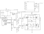
Motor-control-UW1.jpg
 

Hi,

I think it´s caused by crowbar currents in the H bridge.
But your simulation should show this.

***
Isn´t it a waste of time if you simulate the circuit. See that it draws way too much current.. and then test it on the real circuit..
Use a car battery and risk explosion and fire.

I personally am no friend of simulating every circuit.
I use proven circuits
(in this case I´d simply use a high side / low side Mosfet gate driver instead of those 12 pieces - not working - gate driver cricuit)
Then I´d test it on real hardware (in case I´m not sure I use current limiting resistors)
And after the circuit is tested then I´d use the motor.


Klaus
 

A really curious circuit. You are powering the H bridge from an OP output. Apart form the point that the OP can source maximal 40 mA, how is the OP powered?

Also H bridge driving circuit has some problems

- The high-side transistors are never fully turned on, maximum output voltage is supply voltage minus gate threshold voltage.
- The driver transistors and MOSFETs turn off slow, might be O.K. for basic forward/backward control.
 

Hi,

What do the op amp, R12/R13, and R8 do? Is that an LM317 voltage regulator as the op amp voltage reference for a comparator? Why the op amp to supply the voltage when there's a voltage regulator? I ask as it's a set-up I haven't seen before.
 

1. First user questions:

A really curious circuit. You are powering the H bridge from an OP output. Apart form the point that the OP can source maximal 40 mA, how is the OP powered?

I was thinking that its 40mA from the output plus the current from the feedback?

Also H bridge driving circuit has some problems
- The high-side transistors are never fully turned on, maximum output voltage is supply voltage minus gate threshold voltage.

That should be 11.4V normally, which looks enough, since the output voltage is stable even when the batteries drop, because of the linear voltage regulator. The Opamp amplifies the output voltage of the regulator to 12V.

- The driver transistors and MOSFETs turn off slow, might be O.K. for basic forward/backward control.
Why is this so?

2. Second user questions:

Hi,

What do the op amp, R12/R13, and R8 do? Is that an LM317 voltage regulator as the op amp voltage reference for a comparator? Why the op amp to supply the voltage when there's a voltage regulator? I ask as it's a set-up I haven't seen before.

R12 and R13 are to limit the current, because otherwise the motor drains 700A.

R8/R7 was on the schematic when I took it (only the motor control part with the bipolar and MOS FET transistors, everything after the button is a ready schematic that I took).

LM317 is one option, but it has a dropout voltage of 2.5V, so I was thinking of using another linear voltage regulator with a dropout voltage of 0.5-0.9V.

I used the Opamp in order to amplify the voltage to 12V (when the batteries are fully charged they will be at 7.1V, because it takes more voltage to charge the batteries normally, this way we will have a stable output on the end of the voltage regulator, until the batteries drop to a threshold, when the voltage regulator ought to stop working, this way the supply voltage for the MCU and motor is constant and the whole schematic will stop when the batteries drop, preventing undervoltage). The motor is controlled by 12V, but by specification I only have 4 batteries by 1.5V, 2600mA or a VDC source again at 6V, which will help for the work and charge the batteries.

I believe that the principles are accurate, even if its not the best option for a motor control or this schematic? Perhaps if I had to power something with 40mA than my schematic would be appropriate.
 
Last edited:

Hi,

There are many many mistakes in your assumptions, your calculations and your schematic.

I really recommend to start with simpler circuits. You urgently need to study electronic basics.
* voltage regulator circuits
* Opamp circuits
* bjt circuits
* mosfet circuits

****
Opamp.
An Opamp output is always less than it's supply voltage.
--> impossible to get 11.7V

If Opamp output current is specified with 40mA..
--> you can not expect it to output 200mA

Even if you have 12V supply voltage for the H bridge..
--> the high side gate voltage will be less than 12V ... then the bridge output is additionally reduced by V_gs of the Mosfet (about 4.5V)...therefore don't expect more than 7.5V at the bridge output with 200mA.

Linear regulator
..output voltage "even when battery voltage drops"
(Similar as with the Opamp) .. the linear regulator output is always less than it's input voltage.
With an LM317 the input voltage should be 3V higher than the output. This means with 6V input voltage don't expect more than 3V output voltage (at full load)

...and so on...
Useless to discuss all the mistakes...

Klaus
 

Hi,

Perhaps an alternative set-up would be to replace the LM317 and op amp thing with a boost converter IC which has a UVLO pin, that way you can make use of all the useful and helpful information in the converter datasheet, and the many application notes which, if needed, will help to design the circuit based on 6V down to 5V supply, 12V out and xmA for the motor, H-Bridge and the microcontroller.

I don't think a motor needs current limiting, at least not the little motors I've used, they use a lot at turn on, which is a brief spike, then settle to their running current. More or less, the rest of that circuit is okay, the 7805 to power the PIC or whatever you're using would be good, besides necessary, after a boost controller to smooth the switching of the SMPS before the microcontroller.

Personally, may not be the best way of doing it..., I'd make Q3 and Q4 complementary pairs, to get almost the full supply's high and low to turn on and off the MOSFET pairs; would need to make Q1 and Q2 actually work as inverters, to get high and low, again, and swap the code in the PIC to be active low (you have it as active high in that schematic), might not be great but presumably it works. Or, instead of crummy NPN inverters, another complementary pair would mean the active high would be high at the MOSFET gates, much easier... 2 proper inverters make a buffer. ALternatively, if you could find 2 small, and probably not cheap..., SSRs, they could replace Q1 through Q4.

I guess 700A was a typo :), 700mA is too high for standard logic ICs, if not you could have used a logic gate inverter or NAND or AND instead of Q1 and Q2.

Frankly, the original circuit is odd, it looks like "all I had left in the component box was this"/"schematic idea shared on Internet (but not tested or likely to work much)"

Instead of the LM317 as a reference, the well-known TL431 is used in a lot of designs, there are many other voltage reference ICs, they are good - they don't need 3V dropout, to say the least, and provide a more reliable reference voltage than a regulator. TL431 can be used as a reference and comparator in one.

Fast turn on and off of MOSFETs is a good idea, they only "waste" energy when switching on and off, so ideally those moments should be as short as possible.

I think R8 is some kind of mistake, maybe some-one forgot to remove it from the schematic, more likely it is supposed to go from Q6's gate to ground.

IC manufacturer's will have plenty of motor control application notes, which are guaranteed to be reliable information and provide ideas for circuits.

- - - Updated - - -

...just remembered/realised, between PIC and gate driver that H-Bridge circuit needs a level shifter of some kind, as it goes from 5V to 12V, that's why I mentioned an SSR before (although maybe there are PCB mechanical relays that are suitable); a simple-to-implement device which should provide far more base current for the gate drivers than needed (assuming an hFE of at least 100 for Q3 and Q4) is, for example, the SN7407, datasheet attached.
 

Attachments

  • CMOS Hex Buffer Driver 6-Input sn7407 TTL TI.pdf
    1,018 KB · Views: 60

Status
Not open for further replies.

Part and Inventory Search

Welcome to EDABoard.com

Sponsor

Back
Top