Continue to Site

Welcome to EDAboard.com

Welcome to our site! EDAboard.com is an international Electronics Discussion Forum focused on EDA software, circuits, schematics, books, theory, papers, asic, pld, 8051, DSP, Network, RF, Analog Design, PCB, Service Manuals... and a whole lot more! To participate you need to register. Registration is free. Click here to register now.

What is the reason for voltage return in transformer?!

Status
Not open for further replies.

electronicsIUST

Member level 3
Joined
Feb 12, 2017
Messages
67
Helped
0
Reputation
0
Reaction score
0
Trophy points
6
Activity points
575
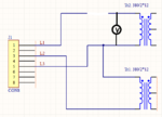
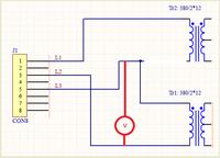
Hi, I have a circuit with two transformer.Each of which has two phases in the primary winding. But the problem is when I disconnect one of phases (for example L1) from Tr2, there is still voltage in that disconnected phase that is due to return voltage of Tr2. What is the reason for this?!

tr2.PNG
 

If you mean there is still a measurable voltage on the transformer side of the break, it depends where your other meter probe is. A voltage is a difference in potential between two points, to measure a quantity you need to specify which points you mean.

If you mean there is still voltage on the secondary of Tr2 when L1 is disconnected, the only possibilities are some magnetic coupling from the other transformer (or nearby alternating field), some leakage from the transformer side of the break to another potential so some primary current still flows or something id feediing the secondary from a different source.

Brian.
 

two causes in your case:
1. Either the transformer are in close coupling or wound in the same formers.
2. or the disconnection may have a circuit loop thro your connectors other end.

which one in this case is to be seen from your arrangement.
 

If you mean there is still a measurable voltage on the transformer side of the break, it depends where your other meter probe is. A voltage is a difference in potential between two points, to measure a quantity you need to specify which points you mean.

If you mean there is still voltage on the secondary of Tr2 when L1 is disconnected, the only possibilities are some magnetic coupling from the other transformer (or nearby alternating field), some leakage from the transformer side of the break to another potential so some primary current still flows or something id feediing the secondary from a different source.

Brian.

Thanks, But I didn't mean the secondary. For example when I disconnect L3 from Tr2 there is still about 330V beween L2 and L3! that is, voltage from L1 goes to L3 through Tr2! and also voltage difference between L1 and L3 is near zero!
 

Each of which has two phases in the primary winding.
Don't know what this means. It's a single-phase transformer. The primary may be connected phase-phase, but what's the purpose of the center tap?

when I disconnect one of phases (for example L1) from Tr2, there is still voltage in that disconnected phase that is due to return voltage of Tr2.
In the shown circuit, there's no "return voltage", unless the load feeds back a voltage between L2 and L3. But you don't show a load, what is it? Show the complete schematic.

Generally, it's unusual to transform a three-phase supply with only two single-phase transformers, because it creates an unbalanced voltage drop.
 

Thanks, But I didn't mean the secondary. For example when I disconnect L3 from Tr2 there is still about 330V beween L2 and L3! that is, voltage from L1 goes to L3 through Tr2!
Do you mean like this ?


The voltage does not go "through". The current goes "through".
 

Don't know what this means. It's a single-phase transformer. The primary may be connected phase-phase, but what's the purpose of the center tap?


In the shown circuit, there's no "return voltage", unless the load feeds back a voltage between L2 and L3. But you don't show a load, what is it? Show the complete schematic.

Generally, it's unusual to transform a three-phase supply with only two single-phase transformers, because it creates an unbalanced voltage drop.

This is part of my circuit. I am sure the voltage is due to Tr2, because when I disconnect this transformer from Tr1 everything is ok!

TR3.PNG

- - - Updated - - -

Do you mean like this ?


The voltage does not go "through". The current goes "through".

No, I disconnect L3 from both transformers! like this. but there is still 330V between L2 and L3! There is no coupling between two transformer.

tr4.PNG
 

The latest schematic makes even less sense. It has only one wire connected to mains.

You should show the actual circuit and how you connect the volt meter. I guess, the result is completely expectable and there's no "return voltage" at all.

This is what I would designate a return voltage

tr2a.png

It can only occur if the load feeds AC voltage back to the secondary of Tr2.

- - - Updated - - -

I see now that the second schematic connects both primary windings in series, so that both are partially powered. That's completely different form the case described in post #1.

Problem with this "phase loss" case is that the voltage share of each primary depends on the load.
 
The latest schematic makes even less sense. It has only one wire connected to mains.

You should show the actual circuit and how you connect the volt meter. I guess, the result is completely expectable and there's no "return voltage" at all.

I think this is better!
excuse me! I didn't understand why there is voltage of phase L1 on other end of primary that is not connected to any phase!

tr6.PNG
 

Connect two light bulbs in series circuit to the mains and both will light at reduced intensity, although the center connection "is not connected to any phase".

As guessed, completely expectable. The only interesting point is the actual voltage share, which depends on secondary load as well as transformer main inductance.

- - - Updated - - -

Seeing a higher voltage across the Tr1 primary, suggests that either Tr2 has a stronger load (contradicting the shown schematic) or has a lower no load impedance for some reason (different transformer type). Did you actually see 330V across Tr1? What's the voltage across Tr2, what's L1-L2 voltage?
 
excuse me! I didn't understand why there is voltage of phase L1 on other end of primary that is not connected to any phase!

View attachment 136962

I do not see any reason to not see voltage across Tr1. What may be weird is the 330 V if the mains is around 330 V because I would expect higher drop in the magnetizing inductance and leakage inductance of Tr2.

Measure the mains L1-L2 voltage.
 
Last edited:
Reading the schematic strictly, there's no DC load connect to the power supply on the secondary. If both transformers are of same type, you'll observe equal voltage share, 1/2 of L1-L2 voltage.

We can just guess that the schematic has errors because it doesn't power V12 and V5 at all.
 
  • Like
Reactions: CataM

    CataM

    Points: 2
    Helpful Answer Positive Rating
Connect two light bulbs in series circuit to the mains and both will light at reduced intensity, although the center connection "is not connected to any phase".

As guessed, completely expectable. The only interesting point is the actual voltage share, which depends on secondary load as well as transformer main inductance.

- - - Updated - - -

Seeing a higher voltage across the Tr1 primary, suggests that either Tr2 has a stronger load (contradicting the shown schematic) or has a lower no load impedance for some reason (different transformer type). Did you actually see 330V across Tr1? What's the voltage across Tr2, what's L1-L2 voltage?

Thanks,
I found that the reason for higher voltage drop is the higher resistance of Tr1's primary winding, it is 3k Ohm while for Tr2 it's 18 Ohm!! L1-L2 voltage is 380V. In this schematic when I disconnect L3 the Tr1 and Tr2 become series, but I didn't understand why there is 220V between L1 and neutral when I disconnect L1! that is, whole voltage of L3 lies on L1 phase and voltage difference between L1 and L3 is near zero!

- - - Updated - - -

I do not see any reason to not see voltage across Tr1. What may be weird is the 330 V if the mains is around 330 V because I would expect higher drop in the magnetizing inductance and leakage inductance of Tr2.

Measure the mains L1-L2 voltage.

thanks, I think the reason for higher drop in Tr1 is higher resistance of its primary winding, it's 3k Ohm while for Tr2 it's 18Ohm! But why when disconnecting L1 all of voltage of L3 drops on L1!!and there is 220 between L1 and neutral?!!
 
Last edited:

Status
Not open for further replies.

Similar threads

Part and Inventory Search

Welcome to EDABoard.com

Sponsor

Back
Top