Continue to Site

Welcome to EDAboard.com

Welcome to our site! EDAboard.com is an international Electronics Discussion Forum focused on EDA software, circuits, schematics, books, theory, papers, asic, pld, 8051, DSP, Network, RF, Analog Design, PCB, Service Manuals... and a whole lot more! To participate you need to register. Registration is free. Click here to register now.

Peltier element controller method, 20Amps bidirectional current

Status
Not open for further replies.
T

treez

Guest
Hello,
We wish to do a Peltier cooler for a Laser diode.
The current will be up to 20 Amps, bidirectional, so we cannot use off-the-shelf switch mode peltier controllers.
Do you think our following method is the most lean?...

We will have two synchronous bucks either side of the peltier element. We will have a single control signal which feeds into both bucks. This control signal will increase the energy throughput of one buck whilst simultaneously decreasing the duty cycle of the other one (and vice versa). We will also use two LTC6101 current monitors as per page 29 of the following to get a current monitor signal which is unipolar but represents current flowing in either direction.
http://cds.linear.com/docs/en/application-note/an105fa.pdf
The error signal between demanded temperature and actual temperature will feed into the current error amplifier to control the peltier current accordingly, and thus control the temperature of the laser diode.
Do you agree that this is the best way forward?
 

Hi,

The only value you give is 20A.
No supply voltage, no peltier voltage, no power...
This makes it hard to help.

My first idea is to use a full bridge circuit...maybe with a series L to smooth current.

Klaus
 
  • Like
Reactions: treez

    T

    Points: 2
    Helpful Answer Positive Rating
Thanks, yes it could be anywhere between +20A to -20A...as you know, the change of polarity meaning change of current flow direction in the peltier.
I've a 10V rail to work with.

I am also toying with a full bridge with fets driven by a single sync buck driver....diagonal pairs on at the same time as normal.

- - - Updated - - -

I wondered if you know of typical resistance values for a peltier element that takes +/-20A?......this is needed so we can see whether or not a 10V rail is enough for us....as you know if its got a big resistance then we'll need to put a big voltage across it to get 20A through it.
We havent decided on the exact peltier element yet..the boss has just told is to get prepared.
 

Why would you want to add heat to a laser diode?
I would expect that self-heating even in the idle
(~ threshold) state is enough. I certainly doubt
that you want full 20A reverse current. This is a
point to get clear on, early. It affects topology
for sure.

Peltier modules are available in a wide variety of
string-lengths (so voltages).

There are folks selling thermoelectric cooling
solutions already for laser diodes. I'd begin by
picking apart the datasheets you can find, for
such products. I expect you'll find some norms
(and maybe a make-vs-buy decision) by doing
so.
 
  • Like
Reactions: treez

    T

    Points: 2
    Helpful Answer Positive Rating
Treez, these Peltier cells are PN junctions, they don't have fixed resistance but act like lossy resistive diodes in the forward direction.

Next thing you should know is peak efficiency is about 30%
Put in one dc watt, about 300mW gets sucked out of the cold side, and about 1.3 watts flows into the hot side.

So for PID control, your heater dc needs to be about a quarter the dc power to your cooler. Say one watt cooling, 250mW heating for +/- 300 mW heating/cooling
If you exceed that ratio, you will have massive overshoot in the heating direction, and it will really struggle to recover from that and regain cooling capacity.

Next thing you should know is rated power is the maximum just before physical destruction, it has nothing to do with maximum cooling capacity.
A huge amount of heat flows through the unavoidable internal thermal conduction from hot side to cold side.
Run with high dc input power, or high output temperature, the net cooling effect easily falls to zero.
Maximum efficiency will be reached with zero temperature differential and at about 5% to 7% of full rated maximum power.

For a 100 watt device run with say six watts input, expect about 2 watts of cooling MAXIMUM. Any more input power and you go backwards to less than 2 watts of cooling.

From the specification sheet, do not just assume 30% efficiency at 100 watts input of cooling. Its more like 2 watts with 6 watts of dc input.

Most people that play with these things come away bitterly disappointed, which is why they are still fringe technology and not in much wider commercial use.
 
Full bridge switcher is the usual topology for bipolar peltier supply, it's usually simpler to design it for symmetrical current although dick_freebird is of course right that heating current demand can be expected much lower than cooling current.

I have implemented a peltier supply for a scientific instrument with a standard unipolar buck switcher and a MOSFET bridge reversal switch.

Peltier voltage mainly depends on the number of couples which can vary of wider range. Expect 50 to 150 mV per couple. Laser thermostats are probably small with few couples, some more for cascaded peltier elements. I guess 1 to maximal 2 V.
 
  • Like
Reactions: treez

    T

    Points: 2
    Helpful Answer Positive Rating
Why would you want to add heat to a laser diode?
As far as i know its because the characteristics of the laser diode are those that are required at whichever temperature, and if the ambient temperature may sometimes be high, then we will have to pick a high regulation temperature.........in other words, its constant temperature that we seek, and as low as possible....but as you know, the peltier cannot cool stuff below the ambient temperature, or below the temperature of the place to where heat is being removed to..

- - - Updated - - -

so we just want the lowest temperature that we can always get to, and as discussed, if sometimes the ambient temperature is say 35degC max, then our chosen temperature must always be that....because if we picked 30degC, then that would be reachable when ambient is 25degC, but not during those times when ambient is 35degC.
I got into a mess explaining that but i hope i unravelled it in the end.

- - - Updated - - -

Full bridge switcher is the usual topology for bipolar peltier supply
I would presume you would agree that the way to drive it would be with a sync buck driver......and inverting the low state and feeding it to the other diagonal pair of fets?...when the peltier current was required to be zero, then the duty cycle would be 0.5 for both diagonal pairs.....or 0.46 when dead times were taken into account.
 

Hi,

Full bridge: How I´d do it:
cooling: Left_low_side=ON, right side = PWM. The higher the duty cycle, the more cooling
heating: right_low_side=ON, left side = PWM. The higher the duty cycle, the more heating

With this you only have on one side the switching loss.

Every microcontroller with hardware PWM can do this.

Klaus
 

Full bridge: How I´d do it:
cooling: Left_low_side=ON, right side = PWM. The higher the duty cycle, the more cooling
heating: right_low_side=ON, left side = PWM. The higher the duty cycle, the more heating
Thanks, i am sure it is workable, but there's the situation of near zero current, where you would be switching between those two modes repeatedly, and this may cause instability.
 

Full bridge would be the way to go, with one of the upper right and left pair dc switched for polarity control, (P channel ?) and just one lower device PWM'd at very low frequency, perhaps at only a very few Hz.

The way I did it was with a class AB integrated audio power module. Strictly linear with +ve and -ve supply rails. Not very efficient, but it was easy because I already had all the parts.
 

Due to the thermal time constant of the peltier system being so long, an analog feedback loop would need very big capacitors in it. Therefore, I believe that a simple microcontroller based slow iterative feedback loop would be best. Do you agree?
 

An integral feedback loop corrects slower and slower as the error decreases, so that is not a problem.
I used a very basic Analog loop and liner power control stage.
If I was going to use PWM, then software would be the obviously better choice.

Yes, an iterative ramping type of correction that slows down as the error becomes less might be the best approach.
A Peltier is not happy changing from heating mode to cooling modes in either direction.
When the error becomes very small, you don't want it to be bouncing back and forth.
I think the slowing down part might be important.
 
  • Like
Reactions: treez

    T

    Points: 2
    Helpful Answer Positive Rating
Re the stabilization issues, I know that lab ovens tend
to use some "D" term weight in the controller so that
the temperature control has a predictive element to it.
This deals with the large thermal mass and sensor lag;
cease heater power "just enough before you get where
you're going" and see less temperature overshoot etc.
 
  • Like
Reactions: treez

    T

    Points: 2
    Helpful Answer Positive Rating
Thankyou for all these great responses

Do you think the attached Peltier current controller topology is the most optimal?
(pdf schematic and LTspice simulation attached)
It’s just a Full Bridge where the Duty Cycle of each diagonal pair determines the direction (& magnitude) of current.
Each diagonal pair is driven by an output of a synchronous Buck driver IC.
The difference between the two current monitor outputs gives the magnitude of current.
As you can see, this topology could easily be commanded to give any magnitude of current in either direction, with a little more circuitry.
Putting this into a frequency compensated feedback loop closed on the temperature is more challenging. If the feedback loop could be done in an “iterative” set/check/modify manner then it would be very simple. All we would need to do is just increment/decrement the current, then read temperature then either increment/decrement the current again, and so on and so forth.
Do you agree that this is the simplest way to do it?

- - - Updated - - -

Yes, an iterative ramping type of correction that slows down as the error becomes less might be the best approach.
A Peltier is not happy changing from heating mode to cooling modes in either direction.

cease heater power "just enough before you get where
you're going"

...Thankyou Warpspeed and dick_freebird
Your responses tell me that the iterative, (software based) simple, "read, set and check, and so on" method of controlling the current/temperature is probably the best way forward, since it appears that around the zero current point offers some challenges for a frequency compensated loop with a Peltier?

- - - Updated - - -

This document appears to suggest that a fully dynamic frequency compensated feedback loop must be implemented for a Peltier system...
https://www.maximintegrated.com/en/app-notes/index.mvp/id/3318
 

Attachments

  • Peltier current controller.pdf
    23.2 KB · Views: 137
  • Peltier current controller.txt
    8.4 KB · Views: 88

That application note is pretty good.
Could be an interesting new experience doing a Bode plot down to millihertz frequencies with a data logger.
 
Last edited:
  • Like
Reactions: treez

    T

    Points: 2
    Helpful Answer Positive Rating
Thanks yes, i think actually checking the gain and phase margin of a frequency compensated TEC Peltier system would be very challenging
 

I suggest you hook up your peltier first with just an an adjustable dc bench power supply.

Get it working in the cooling mode, and find the optimum dc input power for maximum cooling effect.
You will find a definite peak where you get the best cooling performance in degrees per minute cooling (or whatever).
Feeding in too little or too much power will reduce cooling.
The volts an amps to achieve that sweet spot will then be known.
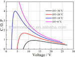
The curve below is about par for the course, usually about 5% to 7% of the maximum power rating is about right. And about a third of the input watts will be net cooling power.

To get any cooling performance at all, will take the worlds biggest heatsink. You need to get right down to ambient on the hot side Every degree you can reduce that will be well worth the effort.
If your heatsink feels warm, you are going to be in trouble.

Getting the same performance in degrees rise per minute when heating is dead easy, and it will take remarkably little power to do it.

The driver then needs to be set up so it duplicates the above conditions in both directions when operating flat out.
Unless you do all this first you will never get it to work, let alone get any kind of predictable dynamic performance from a PID.
 

Attachments

  • Peltier.jpg
    Peltier.jpg
    21 KB · Views: 151
  • Like
Reactions: treez

    T

    Points: 2
    Helpful Answer Positive Rating
Thanks Warpspeed,
In my full bridge peltier current controller (attached here in pdf schematic and LTspice simulation) , giving the fets 50% duty cycle does not necessarily mean zero current in the peltier because of the voltage source which effectively exists in the peltier. So it seems that a Peltier is actually effectively modelled as a unipolar voltage source of a volt or two in series with a resistance of an ohm or two.
In fact, in one direction of current flow, the overall voltage across the peltier element could be zero, as the voltage of the voltage source, and the voltage across the series resistance could cancel, do you agree?
The attached shows two different Peltiers, one with 1A flowing in one direction, and one with 1A flowing in the opposite direction. Even though the magnitude of the current is the same in each case, the duty cycles which produce these currents are not conveniently symmetrical around 50% for the two cases.
This is going to cause problems……because its not going to be possible, due to peltier tolerances, to know exactly which duty cycle will give zero Peltier current….and so there is the chance that any control loop could start off with a duty cycle which puts current say in the heating direction when this was not wanted.
Do you know how this can be mitigated? I mean, it’s not the end of the world, but we really don’t want to ever (even temporarily) put current in the heating direction when we want to cool it. What we want to do is start with a duty cycle that gives zero peltier current, and then gradually increment/decrement it until we have the right system temperature. The thing is, how do we know exactly which duty cycle causes zero current?
 

Attachments

  • Peltier current controllers.pdf
    37.6 KB · Views: 119
  • Peltier current controllers.TXT
    20.7 KB · Views: 85
Last edited by a moderator:

Yes indeed !
Switching between heating and cooling with 50/50% duty cycle is certainly not going to give a net thermal effect of zero.

At zero you want everything switched completely off.
Then PWM starts up and progressively increases in each direction. I would have thought that Analog Devices Peltier controller would have worked that way.
I still think you first need to hook up the Peltier in its final thermal configuration and do some actual testing with steady state dc before you can even start thinking about designing a controller.

I cannot see why you need some PWM system running at Mhz frequencies to generate dc. Just switching max dc current on and off at 10 Hz at the correct duty cycle would work fine. Think how well mains phase control works for heaters and incandescent lamps. Anything faster just generates EMI and switching losses.

The problems of just achieving adequate thermal performance in the cooling direction should keep you entertained for quite some time.
If you can do that, a PWM controller for it should be pretty simple.
 
  • Like
Reactions: treez

    T

    Points: 2
    Helpful Answer Positive Rating
Status
Not open for further replies.

Similar threads

Part and Inventory Search

Welcome to EDABoard.com

Sponsor

Back
Top