Continue to Site

Welcome to EDAboard.com

Welcome to our site! EDAboard.com is an international Electronics Discussion Forum focused on EDA software, circuits, schematics, books, theory, papers, asic, pld, 8051, DSP, Network, RF, Analog Design, PCB, Service Manuals... and a whole lot more! To participate you need to register. Registration is free. Click here to register now.

uc3845 wont work after new replacment..seems new chip needs different start up!

Status
Not open for further replies.

libyantiger

Member level 5
Joined
Aug 10, 2016
Messages
90
Helped
0
Reputation
0
Reaction score
3
Trophy points
1,288
Activity points
2,269
frustration tons of it


i have managed to troubleshoot and confirm that smps have bad uc3845....after ordering one the smps wont work

i have noticed after powering the chip up using external power supply that it will start working when vcc is 8.7vdc


now when i tetsted the start-up voltage i find it to be a 8.4vdc ...i dont know what to do to push it up

it is resistor +capacitor startup circuit so i dont think reducing the start-up resistor will make differenece any ideas?

watch this video of my us3845 testing ...the audio is low but you will manage to hear if you download it


https://www.youtube.com/watch?v=KnRfrD2BtS0&t=8s
 

Is their an electrolytic start up cap that has degraded in capacitance due to age?…try replacing it.
Sorry I cannot hear your video

- - - Updated - - -

Was the power supply ever working?
What voltage do you have on the vdd pin of the uc3845 when it is not working?
Do you have 5v on the ref pin.?
Is the oscillator pin showing a sawtooth?....whats the frequency

- - - Updated - - -

If you load the main output does it start working
If you unload the main output does it start working.

- - - Updated - - -

https://www.ti.com/lit/ds/symlink/uc3845.pdf
According to datasheet the vcc of uc3845 nees to get up to 17.5v (14.5 to 17.5) before it starts working…….if your startup cap discharges below 11.5v (8.5 to 11.5) before the bias winding gets up to 12v or so then it will never get started.
It sounds like you may need to replace the startup cap, and possibly make it bigger.
I cannot tell from your video but it looks lke you are able to get it all up and running when you supply it from a separate psu?
What about the bias rail diode, does it need replacing?...was it of high enough voltage rating in the first place….. I presume it does have a bias rail?

- - - Updated - - -

is it a flyback smps?

- - - Updated - - -

also, Maybe your vref pin cap is too big
 

Would not be surprising that UVLO thresholds are a bit
different between vendors. TI/Unitrode says on at 8.4,
off at 7.6V (reality can be anywhere between). Another
vendor or even another lot could be a couple hundred
mV off from your first part. Also look at the VIN behavior
the first time you slug the line, does it keep sagging
below the turnon threshold and making a "hiccup" mode
or something?
 

Is their an electrolytic start up cap that has degraded in capacitance due to age?…try replacing it.
Sorry I cannot hear your video

- - - Updated - - -

Was the power supply ever working?
What voltage do you have on the vdd pin of the uc3845 when it is not working?
Do you have 5v on the ref pin.?
Is the oscillator pin showing a sawtooth?....whats the frequency

- - - Updated - - -

If you load the main output does it start working
If you unload the main output does it start working.

- - - Updated - - -

https://www.ti.com/lit/ds/symlink/uc3845.pdf
According to datasheet the vcc of uc3845 nees to get up to 17.5v (14.5 to 17.5) before it starts working…….if your startup cap discharges below 11.5v (8.5 to 11.5) before the bias winding gets up to 12v or so then it will never get started.
It sounds like you may need to replace the startup cap, and possibly make it bigger.
I cannot tell from your video but it looks lke you are able to get it all up and running when you supply it from a separate psu?
What about the bias rail diode, does it need replacing?...was it of high enough voltage rating in the first place….. I presume it does have a bias rail?

- - - Updated - - -

is it a flyback smps?

- - - Updated - - -

also, Maybe your vref pin cap is too big


yes the power supply was working one day!!

i really dont know what is the vcc voltage when it working!!

all i know is that i find clearly faulty uc3845 and ordered new ic (10 ices ) ...but i was suprised that when i install it nothing happen

the ic needs 8.7 vdc (by test) to work but while in circuit and powered from its own startup circuit it the voltage is stuck at 8.4vdc i even tried to reduce the vlaue of the startup reisistor a bit nothing works the reference is 0vdc


i will try replacing the cap tommrow and tell u what happens but let us stick to theory


now theoretically the ic have start-up reistor and capacitor that capacitor will start charging going up and up and up in voltage

at some certain moment the ic voltage wil be 8.7vdc and the ic will work ...this will load the cap and starts loosing its voltage but before this happens

the auxciliarry winding voltage will come up and will supply the needed vcc....now the ic is not working at all i wonder what prevents the capacitor from going


up up up in voltage ....to be honest right now no suspect but this capacitor i will change it and let you know but this situation have faced me many many times

and in many times i replace the cap and it never works ...but i will try to stick to theory and let you know the result!

- - - Updated - - -

Would not be surprising that UVLO thresholds are a bit
different between vendors. TI/Unitrode says on at 8.4,
off at 7.6V (reality can be anywhere between). Another
vendor or even another lot could be a couple hundred
mV off from your first part. Also look at the VIN behavior
the first time you slug the line, does it keep sagging
below the turnon threshold and making a "hiccup" mode
or something?

even if there is differnece in vcc requirement the way it works should be straightforward resistors charges cap ...at certain moment there must be voltage on that cap that equals the ic vcc ...that what i know about a 300vdc charging cap using resistor

to be honest i failed one day to fix similiar problem ...new ic wont work ...if powered externally it will work i remember i have changed the vcc cap ...but it never worked

sounds strange ...i even reduced the start-up resistors at that smps but it

...never worked...but sticking to theory it seems a capacitor to me ...if tommorow i replace that cap and smps stays dead then i will be totally stuck
!

- - - Updated - - -

by the way i am not testing smps dc output ....i have removed the mosfet and just testing the uc3845...if it works or not ...since now the uc3845 is unloaded ...it wont lose its vcc voltage so it will continue to work and provide sqaure wave...however no square wave no vcc (at least no 8.7vdc) and 5vdc reference ...

some thing else that attracts my attention ...the start up resistor is terriblly HOT !!

- - - Updated - - -

capacitor replaced with new one nothing happen .....referenece is 0 vcc is 8.4vdc i have tried to reduce the start-up resistor from 75kohm to 35kohm ..the result is that reference have raised to 4.3vdc but still no output and still the vcc at 8.4vdc believe it or not ..........we have straaaaaange situation

to be honest with you i have faced this problem more than 2 times never solved it this time i want to solve it or quit my electronics technician career altogether

this is frustrating...ohm law is being tossed on the wall ...ic uc gets its vcc by cap charge action it would have been solved by cap replacement

if uc 3845 gets its vcc by voltage diveder action the ic should have worked when i reduced the start-up from 75 k all the way to 35k

I AM TOTALLY STUCK PLEASE HELP
 

But you need there to be a main regulated output.
Is it a flyback?
If you havent got a regulated output then how does the bias winding know what voltage to couple to?
Whatever is the voltage on the main secondary, then v(auxiliary) = V(main secondary) * Naux/Ns

It sounds to me that the uc3845 is trying always to draw its bias current through your startup resistor.

Do you have a schematic?

- - - Updated - - -

The startup voltage for uc3845 is up to 17.5v...if you dont get up to that voltage then it will never properly start in the first place.


yes it is flyback

[


friend see the video the uc3845 worked with 8.7vdc and in data sheet they say 8.5vdc so this is confrimed beyond doubt

i have fixed alot of smps based on uc3842 etc all of them will produce sqyare wave with the mosfet removed and will have refrenece voltage

this one have no reference and the start-up seems abit ...just tiny bit lowed than what is supposed

what is needed is 8.7vdc and what is startup is providing is just 8.4vdc ....i dont know to do to get this 0.4vdc let it work

this is mystery and will continue to be so ...have seen this many times ,,,,it is for sure have some thing to do with different ices pacths

some times we install a uc3845 it works some times it never ,,,,,but this time i will not let it go even if i spend 10 years in this repair task

"to be or not to be "

regarding the shcmatic i dont have one it is chinese 3000watt inverter ..and the smps is charger circuit that takes in 220ac and produce 13vdc to charge the battery

i will try to enlarge the capaciitor and further reduce the start up r ...i will let you know ..
 

ok the datasheet i post on #2 above is not too clear whether the startup voltage for uc3845 is 16v or 8.4v.
But if you say you got it working with no more than 8.7v external psu then so it must be 8.7v to get it started.
That is likely to be your problem, because as you know, to start an smps, there has to be a bigger voltage difference between the start and stop voltage...hysteresis.
As you yourself describe, the startup capacitor must not discharge below the "off" threshold before the smps starts self-supplying via its bias winding.
If your start and stop voltages are really close, then you cannnot ever startup.

- - - Updated - - -

i think you need to go for the uc3842 because that definetely has start = 16v and stop = 10v.
But then you must be sure your bias winding can stay above the stop voltage.
sometimes an smps needs a dummy load on the main winding or else the bias winding drops out.

- - - Updated - - -

oh no hang on, the uc3845 has max duty of 50%...so you need to pick uc3844
...although it cannot be said for sure without schematic

- - - Updated - - -

what voltage is coming out of your bias winding?

- - - Updated - - -

If your bias winding is not working, then your 35k resistor is too high ohms to allow through the operating current of the uc3845/2 etc
You need to be sure your bias winding is working
 
ok the datasheet i post on #2 above is not too clear whether the startup voltage for uc3845 is 16v or 8.4v.
But if you say you got it working with no more than 8.7v external psu then so it must be 8.7v to get it started.
That is likely to be your problem, because as you know, to start an smps, there has to be a bigger voltage difference between the start and stop voltage...hysteresis.
As you yourself describe, the startup capacitor must not discharge below the "off" threshold before the smps starts self-supplying via its bias winding.
If your start and stop voltages are really close, then you cannnot ever startup.

- - - Updated - - -

i think you need to go for the uc3842 because that definetely has start = 16v and stop = 10v.
But then you must be sure your bias winding can stay above the stop voltage.
sometimes an smps needs a dummy load on the main winding or else the bias winding drops out.

- - - Updated - - -

oh no hang on, the uc3845 has max duty of 50%...so you need to pick uc3844
...although it cannot be said for sure without schematic

- - - Updated - - -

what voltage is coming out of your bias winding?


the power supply is not working so i cant get voltage out of bais winding....yes uc 3844 seems logical repalcemnt since most manufactures

use 12vdc aux winding then we seems to get uc3844 to replace 3845 with no problem since both are 50% duty cycle


but before ordering one i have to make some start up circuit adjustments and see if it is a fruitful try

- - - Updated - - -

friend i am disconnesting the power mosfet out of the smps so the bais will never works
 

friend i am disconnesting the power mosfet out of the smps so the bais will never works
if the bias doesnt work then you are relying , as you know, on the startup resistor to supply the operating current, and 35k is too high ohms to do this.
I am presuming that your smps starts up by "handing over" from startup capacitor to bias winding...but i do not know this without schematic

- - - Updated - - -

you say it is a charger, so i hope they have put overvoltage protection on the main output for cases when there is no battery connected to it.
Basically you are going to need a load on it which allows the main secondary to get into regulation, then the bias can couple into that and power the uc384x...but if your secondary is shorted say, then there is no hope
 

https://www.youtube.com/watch?v=ukyAHAcy5fc just listen carfully at middle of vidoe sound will be clear


what i have done is to change the value of the resistor from 75k to 35k it was trying to work the ref is 4.2vdc and pulsating

it is what i can define as when uc come up voltage does collapse due to excessive loading of the cap


when i further reduce the resistor to 25k the uc works for a while then shutdown the voltage raise more than 17vdc and the uc works for while prduce wave form and ref but then shutdown


looks like my target resistor is 30k since this will BARLEY allow the uc to work and when the uc come up it will consume some current


that will prevent the cap voltage from raising up with no limits


i feel i am going to fix it ....i will make new video if i done this
 

OK, SO YOU ARE POWERING THE UC384x through the startup resistor...all the time by the sounds of it.....as you say, beware you dont overvoltage the uc3843...consider using a zener/bjt regulator and put your startup resistor in the collector of the bjt...as you know it has to be a high voltage bjt....or just use a protection zener.
 

Your resistor feed has to provide the worst case
standby / pre-UVLO current from the supply you've got
and still make > UVLO threshold. This is another place
that different vendor versions of the 3845 can vary -
even if the spec does not, the reality may very well
be different (within that box).

VIN-(Istby*Rbleed)>Vuvlo or you go nowhere. Might
want to measure Istby between parts that work and
parts that don't.
 
You should put a 20v zener on the vcc pin of the uc384x to ensure you don’t overvoltage it whilst you are testing.
(I am presuming your bias winding puts out less than 20V)
And i am assuming that you are using fet with vgs(max) of 30v
You should try replacing the uc3845 with a ucc38c45…this chip is pin for pin compatible but draws far less operating current.
As you know, If you are not using a bias winding (when it comes up) to power the uc3845, then it’s a waste of time increasing the startup capacitor.

- - - Updated - - -

Is the vref of the uc3845 being used to power other circuitry?
Do you have a large resistor from gate to source of the fet, which could be making the uc3845 draw more current

- - - Updated - - -

You could just put a 10k, 10 watt resistor as the startup resistor, and see if that does the trick...but you must add a 1w, 20v zener to the vcc pin of uc3845 if you do this....but i think you need to change to the ucc38c4x because it is far less operating current

- - - Updated - - -

I presume you are using 220vac mains?...if using 110vac then you will need lower ohm startup resistor
 
SUCESS THANKS MR TREEZ AND FREE BIRD here is the video i have installed a30k 2 watt resistor it was able to supply the needed voltage

and looks like we have situation where the resistor provides just enough to keep the ic working and the ic once working it will start drawing current from cap that is being charger with same dicharge rate of the ic ....so i never get any over voltage condition


still i have to fix the mosfet and see the output and observe if all went well

but primarly speaking it is a suceess!

https://www.youtube.com/watch?v=OgOKjI2yzrU
 

Glad to hear it, its not wonder this happens because the uc384x family daw a surprisingly high amount of bias current....and when you factor in the extra current of driving the fet, its even more current
 

You should put a 20v zener on the vcc pin of the uc384x to ensure you don’t overvoltage it whilst you are testing.
(I am presuming your bias winding puts out less than 20V)
And i am assuming that you are using fet with vgs(max) of 30v
You should try replacing the uc3845 with a ucc38c45…this chip is pin for pin compatible but draws far less operating current.
As you know, If you are not using a bias winding (when it comes up) to power the uc3845, then it’s a waste of time increasing the startup capacitor.

- - - Updated - - -

Is the vref of the uc3845 being used to power other circuitry?
Do you have a large resistor from gate to source of the fet, which could be making the uc3845 draw more current

- - - Updated - - -

You could just put a 10k, 10 watt resistor as the startup resistor, and see if that does the trick...but you must add a 1w, 20v zener to the vcc pin of uc3845 if you do this....but i think you need to change to the ucc38c4x because it is far less operating current

- - - Updated - - -

I presume you are using 220vac mains?...if using 110vac then you will need lower ohm startup resistor

yes sir actually there was zener put it get shorted and i replace it with new one

....i feel i have to buy differnet uc3845 from differnet manufacturers ...and install them one after the other

much easier than playing around with startup resistors and start up caps

...true yes there was some resistor between gate and source i dont know its value however..


i am shamed of my video it is almost voice less unlessu hear in totally silent environment u wont hear any thing


i will make last video more clearer and have good sound ...i will send this thread to other forums ,...there are poeple suffering from this


UC3845 UNCOMPATIBILITY DISEASE


WAIT FOR MY NEXT VIDEO THANKS FOR HELP AND CLUES

- - - Updated - - -

Your resistor feed has to provide the worst case
standby / pre-UVLO current from the supply you've got
and still make > UVLO threshold. This is another place
that different vendor versions of the 3845 can vary -
even if the spec does not, the reality may very well
be different (within that box).

VIN-(Istby*Rbleed)>Vuvlo or you go nowhere. Might
want to measure Istby between parts that work and
parts that don't.


true that is what this thread is all about.....first step i recommend after new chip installation is to feed external dc power and see if the waveform

come out if it comes out then you have to plug ac in ...and see what is the result ...with the mosfet removed you should see wave form coming out

with the mosfet fixed in you may have shutdwon situation ..so better just to see what the chips does with the mosfet out of circuit


if it is not working ...it is an uncompatibility issue ....you have only 2 choices 1st new chip from differnet manufacture
2th start adjusting startup reisistors and replacing startup cap with new ones

and that what i did i replace 70k with 30k and the chip works


see the videos ....not that high quality video thou but if you follow them to end you see the entire process frustration ...determination ...success
 

when you load the main secondary winding, the primary dc bus will dip down and if you are not then supplying the uc38xx by the bias winding then again your power resistor may be too high ohms, because the dc bus will dip down when you start loading the main secondary. Just a thought
 

when you load the main secondary winding, the primary dc bus will dip down and if you are not then supplying the uc38xx by the bias winding then again your power resistor may be too high ohms, because the dc bus will dip down when you start loading the main secondary. Just a thought

not only that once ac applied and mosfet fixed now the chip will spend some current driving the fet ...so resistor only start up wont work

the cap will be discharged ...but the aid will come quickly from the aux winding....i am just far away from my shop and dont have the mosfet in hand


i will show you what happen when i fix mosfet
 

when you load the main secondary winding, the primary dc bus will dip down and if you are not then supplying the uc38xx by the bias winding then again your power resistor may be too high ohms, because the dc bus will dip down when you start loading the main secondary. Just a thought

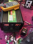
fixed it ! i am happy ...only one little question left ...the start-up resistor is terrible hot ...i wonder if all start-up resistor are usually hot like that ...heck cant touch it! by the way the aux winding is ok it vcc now is 12vdc 444.jpg
 

You should have a diode from your startup supply to the bias winding, and it should get reverse biased by the bias power, so that power does not keep coming through the power resistor after full startup.
Your bias winding should be powering the uc3845, not the power resistor.
You have actually described the proper startup method before.....when you said, dribble current through startup resistor , charge up startup capacitor, then uc3845 starts and then bias windig takes over.

- - - Updated - - -

try this
**broken link removed**

- - - Updated - - -

What about changing to ucc38c4x series, its pin-for-pin the same and drinks far less current.

- - - Updated - - -

What about using LR645
**broken link removed**

...IT SOUNDS LIKE THOUGH YOUR STARTUP RESISTOR IS TOO LOW OHMS, AND (sorry for caps) it is supplying chip all time. Again it sounds like your startup capacitor is not big enough....or your bias winding is not working....or your bias diode has died.
 

Status
Not open for further replies.

Similar threads

Part and Inventory Search

Welcome to EDABoard.com

Sponsor

Back
Top