Continue to Site

Welcome to EDAboard.com

Welcome to our site! EDAboard.com is an international Electronics Discussion Forum focused on EDA software, circuits, schematics, books, theory, papers, asic, pld, 8051, DSP, Network, RF, Analog Design, PCB, Service Manuals... and a whole lot more! To participate you need to register. Registration is free. Click here to register now.

Loop Calibrator design help

Status
Not open for further replies.
Initial accuracy of resistors affecting the scale factor, e.g. R5 will probably worse than 0.01 %, also premium voltage references are typically in the 0.05 to 0.1 % initial accuracy ball park. In so far your calibrator will need calibration against a standard, e.g. calibrated 6.5 digits bench top multi meter. The accuracy of commercial instruments like said 709 will be achieved the same way.

A more complicated point is temperature and long-term drift. You need to analyze the error propagation for each circuit component and select it with respective specifications.
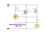
 
Hi,

will this circuit acheives 0.01% accuracy?
A pot is involved in your circuit. So how do you define "accuracy"?

A pot is variable...therefore the output signal is variable, too.
So I find it hard to talk about accuracy here.
Another point is your reference voltage. It seems you use just a 5V power supply signal. It surely is not 0.01% accurate. It will drift with time, with temperature, with load current..

***
Maybe you mean "precision" instead of "accuracy". In other words "repeatability".

Example: Connect it today to a circuit, adjust 10.00mA. And repeat the same without adjusting the pot the next day.
The closer the value to the previously adjusted 10.00mA the better the precision.

Another "precision" test is to adjust it with load "A" and then connect load "B"... and see how good the values match.

But the pot is no good reference. Every time you touch the pot it may change a little. Even acceleration, temperature and humidity may cause it to drift.

***
It depends on the circuit.
In your circuit the change in pot value has 1:1 influence on the output value. If the pot value drifts by 1% then the output value drifts 1%, too.

With "trimming" pots usually have limited "calibration" range. Maybe fixed voltage dividers sets the value to the estimated value and the pot just can modify this value by +/-1%.

--> in your case maybe the pot adjusts the full range from 0...20mA, so 1% pot deviation causes 0.2mA error.
--> in a trimmer (with +/-1% range) configuration.. 1% pot deviation causes just 4uA error.

Klaus
 
Ofcourse I agree with you guys. The reason which I have connected the POT is to change the load resistance.

The circuit which i have posted is just for simulation purpose only. I have components on breadboard and considering parameters like temperature coefficients, etc. In terms of accuracy, Yes I do calibrate the instrument with my 8 1/2 digit keithley multimeter finally. LTC1655 which is a 16 bit DAC and also it has a internal voltage reference of 2.5V. Also I have bought samples of precision references of 0.01% accuracy with 5ppm tempco(from LT, Analog devices). Opamp which I am using is LTC1151 which has tempco of 0.05uV/degree C.

Designing a current source which should not change its output current when load resistance changes upto 1KOhm. Hope I have tried to explain it clearly what I am doing. I knew that my circuit which changes the load current with change in load resistance. I would like someone to help me to design this circuit.

Thank you.
 

Hi,

Yes, now it makes sense.
And there is a good possibility that it may work.

Though 0.01% accuracy is hard to achive...
Clean your PCB to avoid leakage currents.

Klaus
 
Though 0.01% accuracy is hard to achive...

what other parameters should i consider to achieve this accuracy? Have you checked my circuit, will it provide a constant current when i vary the load?

if possible, could you help me to solve this problem.

- - - Updated - - -

Also the load current should be independent of supply voltage. Since the supply voltage will vary by +/- 1V max.
 

To obtain 0.01% accuracy you will require several things:

-The best voltage reference you can obtain. Check Linear Technologies offerings.
-Matched tempco across all your resistors.
-A Digipot, DAC or any other digital means where you can trim and calibrate the end result. Such DAC or Digipot must have non-volatile memory.
-The interface circuit to which access the circuit's memory to a host computer which will actually perform the calibration commands.
-A NIST traceable instrument (or similar calibration standard), to measure your output against.
-Calibration software.

For an optimal calibration, you will have to test and validate at two, or better, three temperatures (hot and cold). If the resulting shift exceeds the tolerance limits at room temperature (a likely scenario), you will require to save on EEPROM those values too. You will have then to incorporate a temperature sensor to the board which the microcontroller will read. The microcontroller, based on the actual temperature, would then perform an interpolation and then compensate by adjusting the Digipot or DAC accordingly.
 
Agree. I shall consider all the points.

For accuracy of 0.01%, I shall calibrate the instrument. Can you please check and tell me whether the circuit provides which i have posted provides constant current when the load resistance changes and minimum change in supply voltage. Or any reference circuit will help.
 

In theory, yes.

But in practice, circuit parasitics, board layout and real components will have an effect.

For instance, the way you connect the sense resistor's grounded side to the rest of the board grounds will have a significant effect.
For any high-performance circuits, the board layout itself is an important, if not the most important, component in your project.

It goes without a saying that a 4-terminal sense resistor is required.
 
Thank you very much.

Do you suggest any other circuit model?
 

Thank you guys for your help. I have tested the circuit on breadboard and it is working fine. I have used IRF420 mosfet(since I have it right now). Should I use BJT or JFET or MOSFET? which one yields the best performance for this application?
 

Hi,

Don't use a bjt in self powered mode (battery powered), because the base current then causes errors.

I have very good experience with the given circuit obove (self powered via DC/DC). Very precise over years now in 24/7 industrial environment.

We have used 1% resistors and BSP318... when we get back a device from the field we see that the calibration still is within 0.1%.

Klaus
 
Should I use BJT or JFET or MOSFET? which one yields the best performance for this application?
I think it's time to read component datasheets and analyze circuit accuracy and error terms yourself. Then you can easily answer the question.

Regarding output transistor, it's obviously so that gate respectively base current appears directly as error current. Other error terms are OP input current, OP offset and finite DC gain.
 
Thank you. I have a doubt in my circuit.

In my circuit, I have connected the load in between the power supply and the mosfet.

Please refer attached pdf file page 12(mA simulate). Will the circuit works for this configuration? IF yes, how it will?

should I modify the circuit something like attached jpg file.
 

Attachments

  • 709-709H-m.pdf
    4.2 MB · Views: 61
  • the-safe-constant-current-source.jpg
    the-safe-constant-current-source.jpg
    29.8 KB · Views: 55

Hi,

I'd say the problem is quite obvious.
You want to regulate the load current. Therefore you have the resistor for current measurement.
But there is a second path: the shunt voltage reference. It's current flows through the current, but not through the resistor.
Therefore it causes an error.

Klaus
 

I worried about, in page 12 (mA simulate mode), the power supply negative and the load negative pins are grounded. That's confusing a lot to me. Should i design a constant current source circuit with load to be connected on high side rather than low side, so that i can connect the load to be grounded. Right?
 

Hi,

You said you want to build something similar to the Fluke...
Then it is absolutely irrelevant if you build a high side or low side current source.
You have two connections to the load and the load won't recognize the difference.
It simply does not know which node you decided to name GND.

Klaus
 

Then it is absolutely irrelevant if you build a high side or low side current source.
Klaus

Shouldn't i consider whether the load is on high or low side?

Please check the attached pdf, on page 11(mA Source), 12(mA simulate). Does my satisfies both the condition. sorry about the ignorance. Im confused. Please help
 

Hi,

Let's say you have a 9V battery, a LED and a current limiting resistor.

Now you have two options:
* connect the resistor in the low side to battery minus
* connect the resistor in the high side to battery plus

Does the LED current (brighness) care if you use the one or the other option?
--> No

****
But maybe you have some special idea in mind. And maybe it makes a difference then..
But then you need to give us your informations. Schematics or at least a sketch.

Klaus
 

Please check the attached image. I tried to explain what I am doing.

In the mA source, there is no problem. Load current depends only on the input voltage and it is independent to supply voltage and load resistance. Checked it.

In the mA simulate, how shall I connect to draw constant current? Since one end is grounded.
 

Attachments

  • IMG_20170316_134140.jpg
    IMG_20170316_134140.jpg
    487.3 KB · Views: 49

Hi,

I´m confused.
like this?

I_Loop.png

Klaus
 

Status
Not open for further replies.

Similar threads

Part and Inventory Search

Welcome to EDABoard.com

Sponsor

Back
Top