ro0ter
Junior Member level 3
- Joined
- Jan 14, 2012
- Messages
- 26
- Helped
- 0
- Reputation
- 0
- Reaction score
- 0
- Trophy points
- 1,281
- Location
- Cluj, Romania
- Activity points
- 1,656
Hello again everybody,
I must say that I am a little ashamed by the fact that I only ask questions and don`t really have the expertise or time to answer other ones... My apologies for this...
I am having some problems with a VW Passat B6 key.. My godson`s key.. He has two of them, yet one emits very weak (the car only opens from near the driver`s door) and the other can open the door from 100+ meters.
I have an SDR and I can clearly see a huge difference between one key and the other. However, I`m not sure about what makes the key emit at such a weak level... I myself own an Skoda Octavia MK2 and my key transmission power is 10 times stronger than the B6`s good key TX. lol
I tried everything:
1. changed the battery
2. provided 3.1v from a bench psu
3. desoldered the oscillator (or is it something else?) and chip, clean everything, solder them back
4. replaced the buttons (he had problems with the locking button, clearly a mechanic failure - button was bent - I replaced all 3 buttons)
Unfortunately nothing helped.
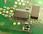
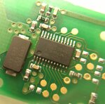
I have only opened the "bad" key for replacing the buttons and (I hoped) to "fix" the bad range as I supposed it had water damage or something.. To my surprise the circuit did not had any trace of liquids, everything is nice and shiny.
I will attach some pictures here, should it be of interest. I suspect either the chip or the impedance matching circuit... but I have no values for those components and they are 0403 (or smaller) smd size.. overkill...
Thank you all!
- - - Updated - - -
The good key (the one to the right) has quite some tx power while the bad key (the one to the left) has very very very little tx power... you can see in the waterfall...
I have also attached some photos of the circuit board, everything seems perfect...
As a side note - my Skoda key makes the entire graph red if near the antenna. Both keys
- - - Updated - - -
The black SMDs are some axially wound inductors with black epoxy/rosin on top. The brown SMDs are definitely MLCCs... yet, what are the white SMDs?
I must say that I am a little ashamed by the fact that I only ask questions and don`t really have the expertise or time to answer other ones... My apologies for this...
I am having some problems with a VW Passat B6 key.. My godson`s key.. He has two of them, yet one emits very weak (the car only opens from near the driver`s door) and the other can open the door from 100+ meters.
I have an SDR and I can clearly see a huge difference between one key and the other. However, I`m not sure about what makes the key emit at such a weak level... I myself own an Skoda Octavia MK2 and my key transmission power is 10 times stronger than the B6`s good key TX. lol
I tried everything:
1. changed the battery
2. provided 3.1v from a bench psu
3. desoldered the oscillator (or is it something else?) and chip, clean everything, solder them back
4. replaced the buttons (he had problems with the locking button, clearly a mechanic failure - button was bent - I replaced all 3 buttons)
Unfortunately nothing helped.
I have only opened the "bad" key for replacing the buttons and (I hoped) to "fix" the bad range as I supposed it had water damage or something.. To my surprise the circuit did not had any trace of liquids, everything is nice and shiny.
I will attach some pictures here, should it be of interest. I suspect either the chip or the impedance matching circuit... but I have no values for those components and they are 0403 (or smaller) smd size.. overkill...
Thank you all!
- - - Updated - - -
The good key (the one to the right) has quite some tx power while the bad key (the one to the left) has very very very little tx power... you can see in the waterfall...
I have also attached some photos of the circuit board, everything seems perfect...
As a side note - my Skoda key makes the entire graph red if near the antenna.
Both keys- - - Updated - - -
The black SMDs are some axially wound inductors with black epoxy/rosin on top. The brown SMDs are definitely MLCCs... yet, what are the white SMDs?