Continue to Site

Welcome to EDAboard.com

Welcome to our site! EDAboard.com is an international Electronics Discussion Forum focused on EDA software, circuits, schematics, books, theory, papers, asic, pld, 8051, DSP, Network, RF, Analog Design, PCB, Service Manuals... and a whole lot more! To participate you need to register. Registration is free. Click here to register now.

[SOLVED] NCV3063 stops working

Status
Not open for further replies.

snipex

Junior Member level 3
Joined
May 23, 2016
Messages
29
Helped
2
Reputation
4
Reaction score
2
Trophy points
3
Activity points
284
Hi

I just got my prototype boards and I'm currently testing it, but there is a problem.
After I turn on the power supply the NCV3063 starts working. I can see the timing oscillator saw and the switching but only for approximately 1ms.
After that the oscillator stops (no more saw waveform) and the switch goes into short circuit.

Do you have any idea what causes this?
 

Hi,

the only useful information in your post is "NCV3063".
According the datasheet the device should operate properly.

Therefore I assume the problem has something to do with:
* your schematic
* your PCB layout
* your device selection
....
But all these things we don´t know.

--> If you need help you need to provide enough information.

Klaus
 

Sorry about that. I checked my schematics and layout and everything seems ok.
I don't understand the device selection line. If it's boost IC then it's NCV3063DR2G in SOIC-8 package.
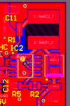
Here is the schematic and layout:
boost.PNG
boost_lo.PNG
 

VCC is the supply voltage. It ranges from 3V to 35V. Vdd_d is the output voltage. It should be around 7V when the input voltage is lower than 7V.
This boost circuit is just to supply the necessary voltage when the supply voltage is too low.

More info:
When I power up the circuit and the boost IC starts to draw current the voltage on the power supply drops to around 1.5V. Thats probably the Vce drop.
 

Hi,

I don´t see a current limit resistor on the PCB (only at schematic). And your inductance is rated to 2.2A saturation current.
How do you ensure that no saturation occurs.
But I don´t think this is the problem.

The PCB layout is OK. I miss the bypass capacitor at VCC. But this shouldn´t be the problem either.


Klaus

- - - Updated - - -

Hi,

the power supply drops to around 1.5V
Why is the power supply not stable? Do you thinkit´s an overcurrent condition?
What exactely is your power supply?
What about installing a larger input capacitor? Does it change anything?

Klaus
 
  • Like
Reactions: snipex

    snipex

    Points: 2
    Helpful Answer Positive Rating
The current limit/sense resistor is on the PCB and is marked as "R1". I used the excel tool that the manufacturer supplies and I simulated the circuit with a similar set-up.
The output current consumption is low (around 50mA) as this is used to power only the microprocessor and another IC, so there shouldn't really be such high currents in the coil.

By bypass capacitor do you mean C11?

The power supply is a normal programmable power supply. The voltage drops because I have a current limit set-up. But the voltage always drops to around 1.5V regardless of what the current limit is (I tried from 200mA to 1A).
Bigger capacitor on the Vcc side is not a problem as it has a C11 (4.7u), another electrolytic (10u) and three more electrolytic (3000u all together).
I will try to add some at the Vdd side. On this side the combined capacitance is 32u.

- - - Updated - - -

Info:

This is the waveform of the timing capacitor. As far as I know this waveform should constantly be in the shape of the saw. As you can see in the picture below the oscillator just stops.

scope_1.png
 

NCV3063 current limiting is set to 2 A. You'll either increase the power supply current limit or increase R1 resistance.
 
  • Like
Reactions: snipex

    snipex

    Points: 2
    Helpful Answer Positive Rating
So is the current limit important? I thought that it was just a protection against shorts.
 

no, the current limit is absolutely essential at all times,ie when there is no fault too....so your output is 7v at 50mA?......then your peak current shoudl be way less than 2A, and your 100milliohm sense resistor is way too small.

You do realise that the booster has no isolation from vin to vout, and that if vin = 35v then vout will be 34.3v...isnt that going to blow your micro?
 
  • Like
Reactions: snipex

    snipex

    Points: 2
    Helpful Answer Positive Rating
I increased the current limiting resistor to 200mOhms so that should give me a current limit of 1A. It's working now.
Thank you all for helping.

I know that there is no isolation. Microcontroller has a separate 5V LDO regulator. Boost switcher is there to power the mosfet driver in case of low supply voltage. It can handle up to 45V.
 

Status
Not open for further replies.

Similar threads

Part and Inventory Search

Welcome to EDABoard.com

Sponsor

Back
Top