Continue to Site

Welcome to EDAboard.com

Welcome to our site! EDAboard.com is an international Electronics Discussion Forum focused on EDA software, circuits, schematics, books, theory, papers, asic, pld, 8051, DSP, Network, RF, Analog Design, PCB, Service Manuals... and a whole lot more! To participate you need to register. Registration is free. Click here to register now.

[Moved]: discrete time integrator with transfer function = 1/(1-Z^-1)

Status
Not open for further replies.

Vivek_2017

Newbie level 4
Joined
Feb 3, 2017
Messages
6
Helped
0
Reputation
0
Reaction score
0
Trophy points
1
Activity points
66
Hi,
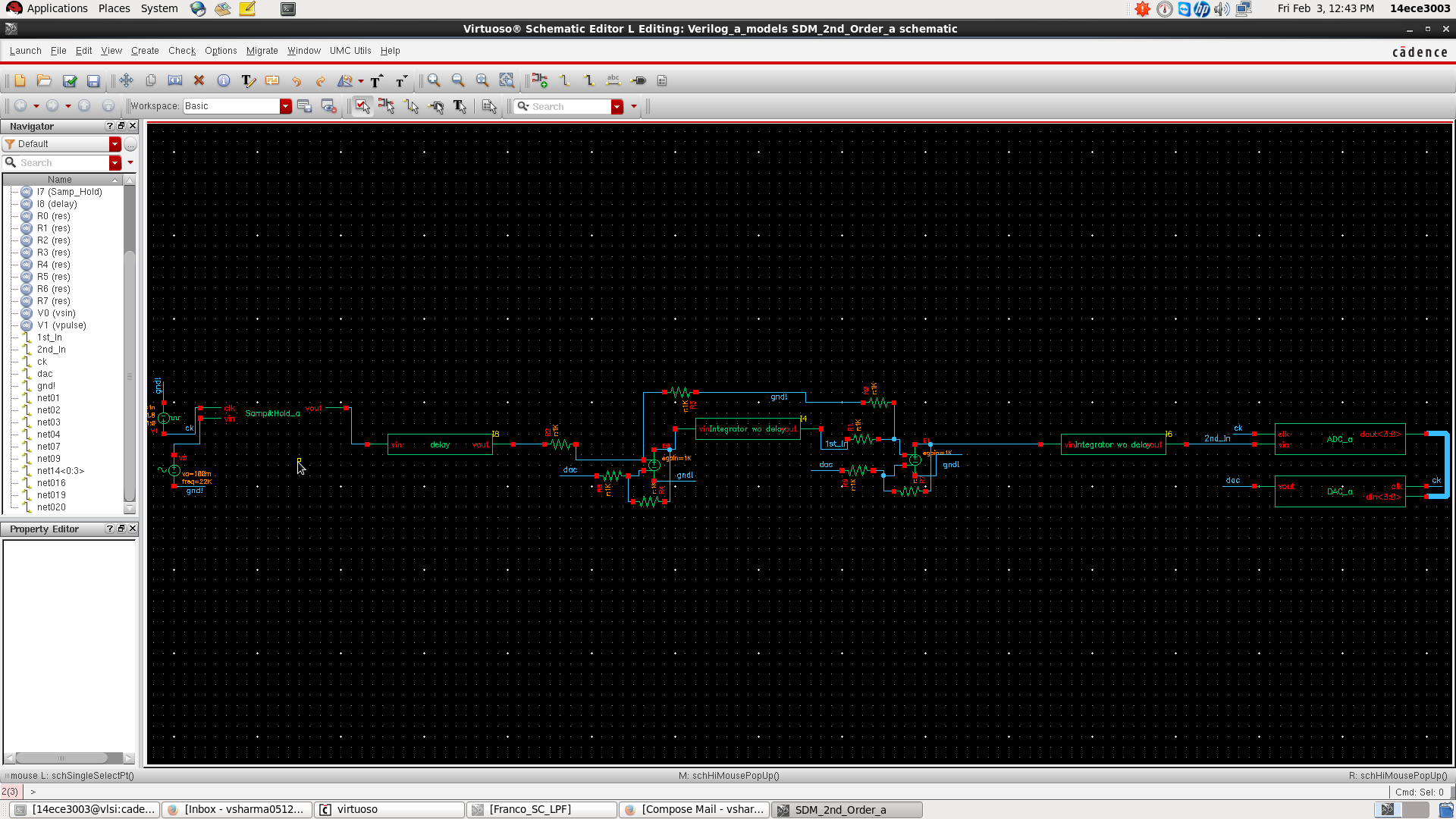
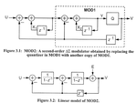
I am designing a discrete time integrator with transfer function = 1/(1-Z^-1) using model writer of the cadence virtuoso, below is the verilogA code of the integrator. But I am getting a gain of more than 1000 in the output, when applying an input signal of 900 uV (p-p).

I added the screenshot of the schematic as well as the transient output response of the integrator.

Screenshot.pngScreenshot-1.png


Code Verilog - [expand]
1
2
3
4
5
6
7
8
9
10
11
12
13
14
15
16
17
18
19
20
21
22
23
24
25
26
27
28
29
30
31
32
33
34
35
36
37
38
39
40
41
42
43
44
45
46
47
48
49
50
51
52
53
// FUNCTION: Z-domain Filter
// VERSION: $Revision: 2.8 $
// AUTHOR: Cadence Design Systems, Inc.
//
// GENERATED BY: Cadence Modelwriter 2.31
// ON: Thu Feb 02 08:59:10 IST 2017
//
// Description: N degree Transfer functions of H(z)
// May be specified as a Polynomial or as Poles and Zeros.
// 
// Complex Poles and Zeros must have conjugates.
// 
// 
// This model is an example, provided "as is" without express or
// implied warranty and with no claim as to its suitability for
// any purpose.
// 
// PARAMETERS:
// first = Delay before taking first sample [S]
// samp = Sampling period [S]
// trans = Transtion time [S]
// 
 
`include "discipline.h"
`include "constants.h"
 
// model ztrans 


// Z-domain in Numerator-Denominator form
// Filter order is: 1 / 2 
  
module ztrans (vin, vout);
  input vin;
  output vout;
  electrical vin, vout;
  parameter real samp = 3.90u from (0:inf); 


// nxN is numerator of degree N.
// dxN is denominator of degree N.
  parameter real nx0 = 1.0;
  parameter real dx0 = 1.0;
  parameter real dx1 = -1;
 
  analog begin
  V(vout) <+ zi_nd( V(vin), { nx0 }, 
  { dx0, dx1 }, samp);
  end
 
endmodule

 
Last edited by a moderator:

Re: discrete time integrator with transfer function = 1/(1-Z^-1)

I see a gain of about 50 in the waveforms which should be expected for the given parameters. (T=3.9 µs, f = 1 kHz).
 
Re: discrete time integrator with transfer function = 1/(1-Z^-1)

Thanks FvM for the reply,
First I apologize for typing gain = 1000.
1. But this is an ideal delay free integrator isn't it suppose to give gain = 1/sqrt(2) only.
2. when I am giving input 200 mV (peak-peak) then the output is in kVs.
3. I am simulating in cadence virtuoso IC 6.1.5, so is there any settings required to converge the output, as I think the output of the ideal delay free integrator is not converging.
Please correct me where I am wrong.
 

Re: discrete time integrator with transfer function = 1/(1-Z^-1)

1. Why 1/sqrt(2)? It's not time continuous integral with time constant 1s, it's time discrete integral with 3.9µs sampling interval, roughly equivalent to 3.9 µs integrator time constant. Gain for sine input is 1/(ω*3.9µs).

3. Ideal integrator output never converges, neither continuous nor time discrete. External feedback or at least initial conditions needed.
 
Re: discrete time integrator with transfer function = 1/(1-Z^-1)

Still there exist many bugs in Z-domain function of Verilog-A.
So I don't recommend use Z-domain function of Verilog-A.

Use "pllMMLib/z_integrator_digi".
 
Re: discrete time integrator with transfer function = 1/(1-Z^-1)

An integrator is just that - it takes the existing sample, scales it and accumulates the result. It will happily count towards infinity (infinite gain) if the input stays positive or negative for a long time (I.E. low frequency AC or DC)

I wonder if an ideal integrator is really what you want or if you want the equivalent of an RC filter which is slightly different (has capped DC gain, often 1).
 
thanks for the reply FvM.

Thanks for the reply pancho_hideboo, but What is "pIIMMLib" which library is this??

Thanks for the reply asdf44,
Please see the image attached with this reply,


https://obrazki.elektroda.pl/9756054400_1486740617.png

This is a second order sigma-delta modulator (all blocks are ideal verilogA models only) schematic design, problems with this is:
1. Although there is a negative feedback, the output of the integrator is very high in kVs due to which the ADC (4-bits) always give logic 1 and corresponding the DAC (4-bits) output is Vmax (= 1.8 V in this case).
2. If we use all the blocks of the schematic except the integrator the system works perfectly fine (i.e ADC, DAC, Sample&Hold and vcvs blocks work fine).
3. The input signal is 200 mV (peak-peak) and frequency = 22 kHz, while the sampling clock is operating at 2.8 MHz.
 
Last edited by a moderator:

Re: [moved] discrete time integrator with transfer function = 1/(1-Z^-1)

Thanks for the reply pancho_hideboo, but What is "pIIMMLib" which library is this??
"pllMMLib" is located in same directory as "rfLib", "bmslib", "pllLib" and "ahdlLib" which are shipped with Cadence dfII.

"Your_CDS_Install_Directory"/tools/dfII/samples/artist

2. If we use all the blocks of the schematic except the integrator the system works perfectly fine (i.e ADC, DAC, Sample&Hold and vcvs blocks work fine).
Don't use zi_nd() of Verilog-A.
 

Attachments

  • 170211-020937.png
    170211-020937.png
    31.8 KB · Views: 235
Last edited:

Status
Not open for further replies.

Part and Inventory Search

Welcome to EDABoard.com

Sponsor

Back
Top