Continue to Site

Welcome to EDAboard.com

Welcome to our site! EDAboard.com is an international Electronics Discussion Forum focused on EDA software, circuits, schematics, books, theory, papers, asic, pld, 8051, DSP, Network, RF, Analog Design, PCB, Service Manuals... and a whole lot more! To participate you need to register. Registration is free. Click here to register now.

controller for single phase bldc motor

Status
Not open for further replies.

AgnesAnna

Newbie level 6
Joined
Oct 22, 2016
Messages
12
Helped
0
Reputation
0
Reaction score
0
Trophy points
1
Activity points
119
controller.png

Hi all,

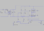
Here i have attached the controller circuit schematics(done in LTSpice) for single phase BLDC motor. The basic working is that based on the hall sensor signal, the current output of H bridge inverter should reverse. Across points A & B we'll be connecting the motor. Here the pulse signal represents the hall sensor output signal. The problem with this circuit is that when load (50 ohm) is connected across A & B, the required voltage and current signals are not getting. The voltage signal should be a square wave of 72 Vp-p (Vmax=36V) but what i am getting is a 4.8Vp-p square wave.Also, output of zener diode shold be 36V but 5V is the output with load.Without load its working fine. What could be the reason? Any suggestions to improve the circuit?
 

Hi,

R11, R12, R13 limit the current to an almost useless value.

Klaus
 

R11, R12, R13 limit the current to an almost useless value.
Not particularly. Obviously C1 is intended to deliver the relevant current (about 70 mA).

A brief calculation clarifies that the motor consumes the tenfold current. On the other hand, D1 will already burn at 10 mA or so. The circuit doesn't seem to be well considered in any regard.

My suggestion: Open trash bin, put schematic in, close trash bin. Or think about a regular transformer or switch mode power supply.
 

Status
Not open for further replies.

Part and Inventory Search

Welcome to EDABoard.com

Sponsor

Back
Top