Welcome to our site! EDAboard.com is an international Electronics Discussion Forum focused on EDA software, circuits, schematics, books, theory, papers, asic, pld, 8051, DSP, Network, RF, Analog Design, PCB, Service Manuals... and a whole lot more! To participate you need to register. Registration is free. Click here to register now.
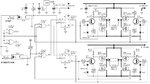
The schematic doesn't even put the PMOS symbols correctly in place, it's probably rather a "design idea" than a working circuit. There are more problems like missing dead-time generation and non-optimal gate voltage range.
The stepper motor is operated with constant voltage and no option to turn off or at least reduce the motor power in idle state. If you take the circuit as is (after correcting obvious drawing faults), you only have to adjust the supply voltage for a suitable continuous motor voltage and won't necessarily need additional protection except for a fuse preventing the circuit from catching fire.
As far as I understand, NMOS is driven by constant 5V supplied CMOS logic, PMOS by 4 to about 10 V through transistor level shifter, variable according to motor supply voltage. The used standard MOSFETs are not fully turned on by gate voltage below 7 - 8 V. But the solution may work for lower motor currents.
MOSFET turn-on should be delayed against turn-off, that's not possible with the present circuit.
Are you so in love with this circuit that you won't
consider designing with bridge driver ICs, which take
care of many of the issues raised here (and probably
cost less than the pile-o'-parts that work less well)?
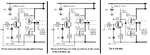
The gate signal connection in the leftmost circuit is not identical with the original circuit. Why did you flip the inputs along with correcting the PMOS terminals?
The suggested corrections are not essentially better, depending on the supply voltage either the transistors won't be fully turned on or you get shoot-through. No chance to work for the supply voltage range indicated in the original schematic.
The gate signal connection in the leftmost circuit is not identical with the original circuit. Why did you flip the inputs along with correcting the PMOS terminals?
Just now I notice that the upper and lower original H-bridges are different. I showed only the upper one.
1) The Pmos is a follower so its gate voltage must be much higher than the supply voltage for it to fully turn on. Depending on how high is the supply voltage, it will either not turn on or it will partially turn on and fry.
2) I turned the Pmos around so that it is a switch like the OP said, but the transistor driving it inverts and causes both Mosfets to turn on at the same time and they both fry.
3) I joined their gates so that one Mosfet turns on when the other turns off but there is shoot through current when they switch.
I can't be bothered analysing the bottom H-bridge.
This site uses cookies to help personalise content, tailor your experience and to keep you logged in if you register.
By continuing to use this site, you are consenting to our use of cookies.