Continue to Site

Welcome to EDAboard.com

Welcome to our site! EDAboard.com is an international Electronics Discussion Forum focused on EDA software, circuits, schematics, books, theory, papers, asic, pld, 8051, DSP, Network, RF, Analog Design, PCB, Service Manuals... and a whole lot more! To participate you need to register. Registration is free. Click here to register now.

op amp output voltage derivation

Status
Not open for further replies.

AssemblyLine

Member level 1
Joined
Nov 1, 2013
Messages
35
Helped
0
Reputation
0
Reaction score
1
Trophy points
1,288
Activity points
1,608
I need some help in deriving the output voltage of the following circuit
My calculations does not seem to match the simulations
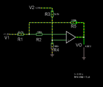
Untitled.png

I have computed the output voltage as
(K1/K3)*V2 - (K2/K3)*V1
K1=R4/(R3+R4)
K2=( R2//R5 ) / ( R1 + R2//R5 )
K3=( R1//R2 ) / ( R5 + R1//R2 )
Numerically it leads me to Vo=4.58*V2-4.21*V1 ...But it does not match the simulation
 

Hi,

For an about ideal OPAMP the input current is considered to be zero, therefore there is no voltage drop across R2.
--> you don´t need to care about R2.

R3 and R4 are a voltage divider.
--> Calculate the voltage at IN+

--> IN- has the same voltage as IN+

Current in R1: I_R1 = (V1- V_IN-) / R1
The same current is through R5.

Voltage across R5: V_R5 = - I_R1 x R5

Output voltage: V_out = V_IN- + V_R5

Klaus
 
Your opamp does not have a power supply so it will not work.
Your output voltage is shown with no polarity.
 

@KlausST : Thank you, My mistake was to consider R2 as being tied to GND

@Audioguru: That it is not the schematic of a real circuit, just a simulation. If the power supply it is not shown it does not mean that it is inexistent. And by convention 5V means +5V.
I don't know anywone who will asume that 5V it is in fact -5V. In the simulation the op amp supply is +12VDC
 

I need some help in deriving the output voltage of the following circuit
My calculations does not seem to match the simulations

View attachment 135269

I have computed the output voltage as
(K1/K3)*V2 - (K2/K3)*V1
K1=R4/(R3+R4)
K2=( R2//R5 ) / ( R1 + R2//R5 )
K3=( R1//R2 ) / ( R5 + R1//R2 )
Numerically it leads me to Vo=4.58*V2-4.21*V1 ...But it does not match the simulation

Here are the node calculations. vx is the node between r1 and r2. It is also the voltage of the op-amp inputs. vo is, of course, the op-amp output voltage. An infinitesimal amount of current is assumed to exist in R2 to sustain electrical conductivity so that vx and the op-amp inputs are at the same voltage. The result for vo is a complicated expression, but it matches quite closely with Falstad. If I knew what current Falstad assumed through r2, I could give an exact result.

fionut.JPG

Ratch
 

Attachments

  • Jonathan56.JPG
    Jonathan56.JPG
    19.9 KB · Views: 87
Start with + input, the easy one.
VIN+ = 2.5V*(100k/(25.9k+100k)) = 2.0V.

Now ignore R2 since nobody's telling you input bias
current. Though depending on op amp this could
matter slightly. VIN- must equal VIN+. So now
I(V1) must equal (2.0-1.3)/23.7K or 29.5uA.

This must also be the current through R5, to 2.0V
(on VIN-). So VO=2.0+29.5E-5*1E5 or 4.95V.

There is a ~2% discrepancy. You might look at
whether there is actually input bias current on the
op amp subcircuit (probe R2).

There may also be the "inputs" of limited gain (gain
error), common mode rejection and so on. On a good
real op amp these should be on the order of 0.01%
each. But we know nothing about the particular one
here.

If you use the correct value for r3, you will get the same answer I did.

Ratch
 
Status
Not open for further replies.

Similar threads

Part and Inventory Search

Welcome to EDABoard.com

Sponsor

Back
Top