Continue to Site

Welcome to EDAboard.com

Welcome to our site! EDAboard.com is an international Electronics Discussion Forum focused on EDA software, circuits, schematics, books, theory, papers, asic, pld, 8051, DSP, Network, RF, Analog Design, PCB, Service Manuals... and a whole lot more! To participate you need to register. Registration is free. Click here to register now.

EEPROM Write When Power Loss PIC18F2520

Status
Not open for further replies.

nis2311

Member level 2
Joined
Nov 19, 2016
Messages
52
Helped
0
Reputation
0
Reaction score
0
Trophy points
6
Activity points
501
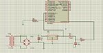
I want to store the data when POWER loss or Down.
So I connected to the interrupt Pin with help of diode
I used 1000uf/25V capacitor to store the power to write EEPROM DATA.
But interrupt working only when Gnd to VCC trigger but in my case trigger will be VCC to GNd.
I attached My circuit and code also.Please Find it,

Example Code:

Code:
void interrupt zero()
{
if(INT0IE && INT0IF)
{
eeprom_write(5,s);
}
}
void main() 
{
ADCON0=0x00;
ADCON1=0x0F;
PORTB=0X00;
PORTA=0X00;
TRISC=0X00;
TRISA=0X00;
TRISB=0X03;
INT0IE=1;
PEIE=1;		//Enable Peripheral Interrupt
GIE=1;		//Enable INTs globally
INTEDG0=0;
while(1) 
{
address(0x80);
dispstr("____ME___________");
s++;
_delay_ms(100);_delay_ms(100);_delay_ms(100);_delay_ms(100);_delay_ms(100);_delay_ms(100);_delay_ms(100);_delay_ms(100);_delay_ms(100);
}
}
 

Attachments

  • ckt3.jpg
    ckt3.jpg
    204.3 KB · Views: 134

Why did you opened another thread for the same project ?

What is your FOSC. I will write a code for you. You test my code. Maybe problem is in software.
 

Proteus will not simulate that. Power is always connected. Power pins are local.
And it is bad idea to impement writing inside interrupt.
 

It works. See attached video if you don't have Proteus 8.5 SP1. I also tested the project with PIC18F46K22 on hardware and it works fine. Test the attached .hex file on hardware. The power supply of PIC circuit if not battery operated should have atleast 1000 uF at input and output of LM7805.
 

Attachments

  • External Interrupts With PIC18F2520.rar
    183.8 KB · Views: 85

Hi,

It's better to connect the high value capacitor at the voltage regulator input.
Then use a comparator to detect when this input voltage goes below 9V (or any other useful level).

This ensures a valid VCC level during Eeprom write operation.

Klaus
 

Yes, it is better to do a KlausST mentions. Use a 10000uF 50V capacitor at the input of 7805. 10000uF 50V is easily available. Then use a voltage divider and scale the 7805 input voltage to adc input pin. If power goes then capacitor voltage slowly decays and when ADC input goes below 4V then start writing to eeprom. During this time there will be still 5V power for PIC.
 

I checked this program in PIC18F452 , the program working perfectly ,I don't known why this program concept not working in PIC18F2520.
Please give any suggestion to me. I think any problem in IC is there I want to buy new IC and want to check it..........
 

If it has INT0, INT1 and INT pins then check with INT1 or INT2 pin.
 

I checked those pins also INT0 , INT1 , INT2 but same problem...........
 

Maybe you need to buy a new PIC18F2520 and try the code with proper pulse detection circuit. Don't connect to high current circuit. Maybe it has damaged the INT module inside the PIC.
 

Get yourself one of the many regulators which have an output flag which will tell the microcontroller of an impending voltage drop.

Most of the major semiconductor vendors offer such regulators. Perform a web search.
 

I checked this program in PIC18F452 , the program working perfectly ,I don't known why this program concept not working in PIC18F2520.

The above routine is just part of the whole code, and it hasn't any directive to handle the fuse of the brown-out-detector, which sugests that you likely programmed it differently on each device.
 

Same Problem in New IC PIC18F2520. It is working well in 40 Pin PIC18F452 but is not working PIC18F2520 .
My problem is when Interrupt Program want to run when RB0 is 5 volt to GND connected.
But my concept is working well in PIC18F452.
Help me to solve the Problem.

Code:
#include<htc.h>
#define led1 RA0
#define led2 RA1
void delay(unsigned int a)
{
while(a--);
}
void interrupt zero()
{
if(INT0IE && INT0IF)
{
led2=1;
}
}
void main() 
{
ADCON0=0x00;
ADCON1=0x0F;
PORTB=0X00;
PORTA=0X00;
TRISC=0X00;
TRISA=0X00;
TRISB=0X0F;
delay(65000);delay(65000);delay(65000);delay(65000);delay(65000);delay(65000);delay(65000);delay(65000);delay(65000);
INT0IE=1;
PEIE=1;		//Enable Peripheral Interrupt
GIE=1;		//Enable INTs globally
INTEDG0=0;
while(1) 
{
address(0xC0);
dispstr("____ON___________");
led1=1;
delay(65000);delay(65000);delay(65000);delay(65000);delay(65000);delay(65000);
led1=0;
delay(65000);delay(65000);delay(65000);delay(65000);delay(65000);delay(65000);
}
}
 

Problem Solved by using Optocoupler.
Led side is given to 5V power using 1K resistor.
Transistor side I connected one for GND and other to RB0.
If 5v is off means RB0 goes to null state and Interrupt is working.
 

Status
Not open for further replies.

Part and Inventory Search

Welcome to EDABoard.com

Sponsor

Back
Top